

 English
 Deutsch
News
Home / News / Industry News / 24V to 120V Relay Selection Guide: Specifications, Applications and Installation Tips
A newly installed production line is ready to run. The PLC outputs are 24V DC. The solenoid valves, indicator lamps, and small motors on the line operate at 120V AC. Without a correctly specified 24V to 120V relay, the two circuits cannot talk to each other. The machine stops before it ever starts. The relay is the bridge, and choosing it correctly is the difference between a clean handoff and a repeated maintenance ticket.
Conclusion up front: Match the coil to your control voltage, match the contacts to the load current, and add monitoring for critical circuits. A 24V DC coil with 120V AC rated contacts is the general-purpose solution for most industrial control panels.
A 24V to 120V relay is an electromechanical switch that accepts a 24V DC control signal on its coil and switches a 120V AC load on its contacts. The coil draws a small current, generates a magnetic field, and pulls a moving contact closed or open. The coil and the contacts are physically separated and electrically isolated. This isolation prevents transients from the load side from reaching the controller.
24V DC is used broadly in industrial control because it is low enough to limit the shock hazard, high enough to resist electromagnetic noise, and easy to obtain from DIN rail power supplies. 120V AC remains common for lighting, HVAC equipment, and standard outlets. A 24V to 120V relay provides the clean interface between these two domains.
In practice, the relay is the single component that makes the two voltage worlds coexist inside one control cabinet.
Before you purchase relays, you need to compare a small set of parameters. The four most important are coil voltage, contact rating, isolation, and mechanical life.
| Specification | Why It Matters |
|---|---|
| Coil Voltage | Must match the 24V DC controller output |
| Coil Resistance | Determines current draw and control circuit load |
| Contact Rating | Must exceed the 120V AC load current |
| Contact Form | Defines how many circuits can be switched |
| Isolation Voltage | Protects the control side from transients |
| Mechanical Life | Number of operations before replacement |
| Response Time | Critical for fast-switching applications |
When reviewing a relay datasheet, start by confirming the coil voltage matches your controller output. Then verify that the contact rating covers the steady-state current and the inrush current of the load. Isolation voltage ensures the magnetic separation is sufficient. Mechanical life tells you how many operations to expect.
Common applications include:
In automation, PLC digital outputs are almost always 24V DC. When switching 120V AC solenoid valves, fans, or heaters, a relay is the standard interface. It duplicates the control signal and provides galvanic isolation, which protects the PLC from load-side faults.
Commercial HVAC controllers typically use 24V logic. The actual compressors and fans run at 120V or higher. A relay bank inside the control cabinet connects the logic side to the power side. This arrangement keeps the low-voltage controller away from high-voltage wiring.
Building management systems use 24V DC inputs and outputs. For 120V AC lighting circuits, relay panels switch entire banks of lights. This mode is used in offices, parking garages, and warehouses, where centralized lighting schedule control is required.
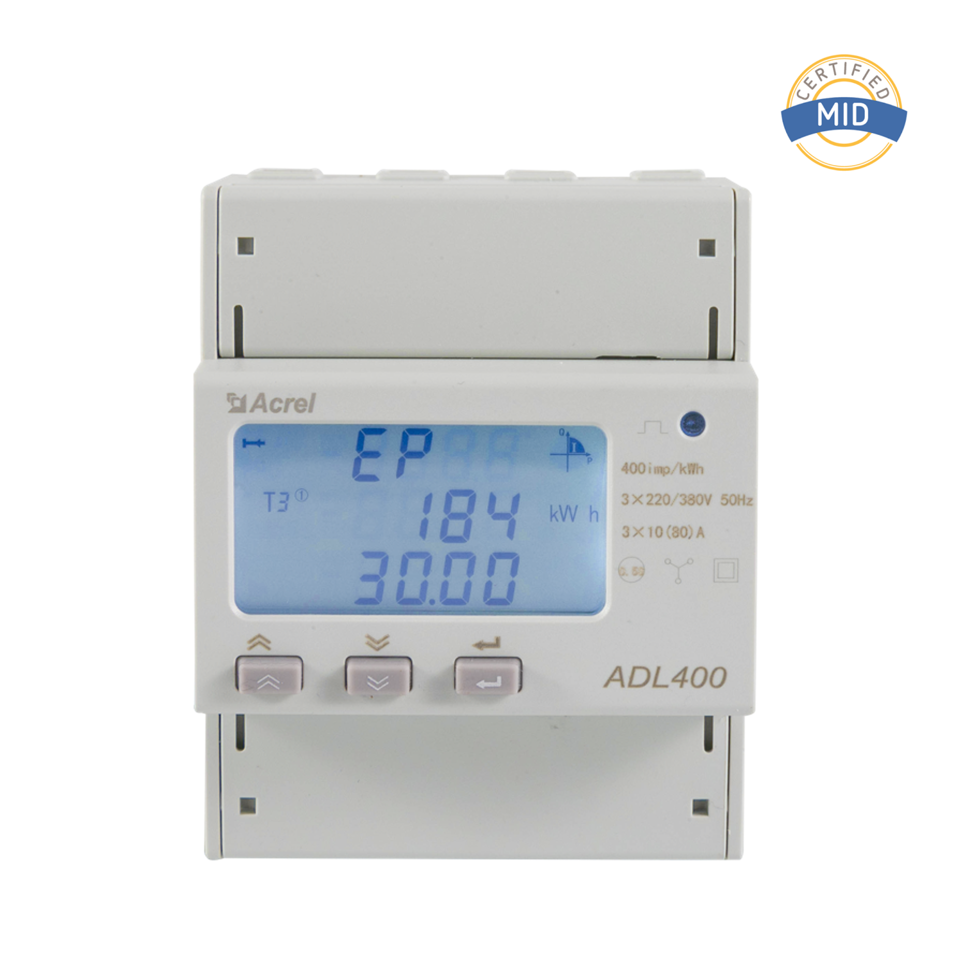
IT equipment in data centers operates on 120V AC or 208V AC. Remote power management needs to switch power to specific racks or PDUs. Relays provide the isolated switching function, and current transformers and energy meters monitor the power that the relay distributes. This combination allows operators to control and measure each circuit.
Start with the load, not the coil. If the load is a motor, solenoid, or transformer, the inrush current can be five to eight times the steady-state value. Select a contact rating above the inrush, not just the running current. This margin prevents contact welding and premature failure.
Resistive loads such as heaters and incandescent lamps switch cleanly. Inductive loads such as motors and AC coils create arcs when contacts open. For inductive loads, choose a contact rating with at least 20-30 percent margin.
The inrush current of a motor can be several times the running current. A relay rated for 10A continuous can face a 50A inrush for a fraction of a second. If the contact is not rated for the inrush, the contacts will arc and melt. Always review the inrush specification.
Relays are available in blade, plug-in, and DIN rail formats. For control panel retrofit, DIN rail mounting is standard and makes replacement quick. Compact relays save panel space while preserving switching capability.
Look for UL, CE, and IEC markings for international projects. If the machine is built for export, a relay with the relevant certifications avoids compliance delays during inspection.
A reliable 24V to 120V relay is one element of a robust circuit. Contact wear, overheating, and load-side faults can all cause downtime. By adding protection and monitoring equipment, you build a system that can prevent failure before it causes damage.
For the load side, a protection relay such as Acrel's AM2SE protection relay can be connected to monitor and protect the switched circuit. It provides measurable protection and can be installed together with current transformers and signal conditioners.
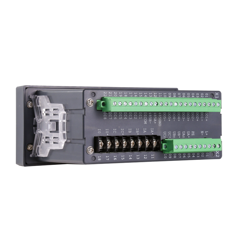 Acrel AM2SE Protection Relay for Medium Voltage 10kV ApplicationsThe AM2SE protection relay is tailored for 10kV systems, with modular design, ANSI protection functions, and communication options. It suits ring main units and MV switchgear, ensuring reliable feeder protection and easy integration.View Product →
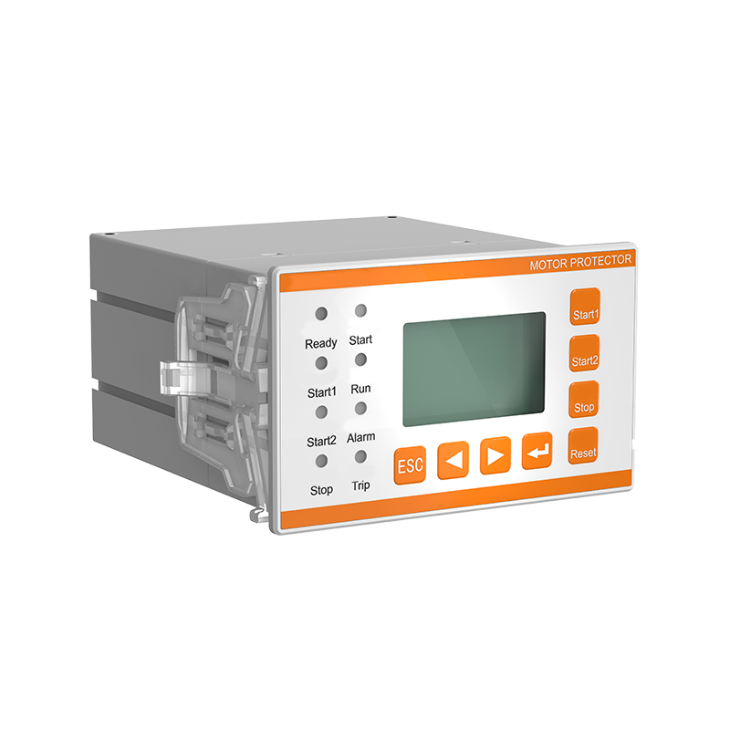
For motor loads, a Profibus-DP motor protector with programmable digital outputs can be wired into the control loop. It detects overload, leakage, and phase loss, and sends the alarm state back to the controller.
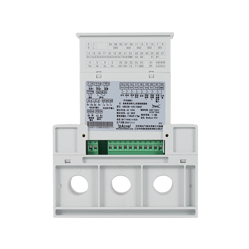 Acrel ARD2M Motor Protector with Profibus-DP CommunicationDesigned for low-voltage motor circuits, the ARD2M offers programmable I/O, start control, and Profibus-DP connectivity. It provides comprehensive motor protection and monitoring, making it ideal for industrial automation.View Product →
When you need to transmit signals from the 24V control circuit to a monitoring system, a signal conditioner provides isolation and scaling. Acrel's BM800 series signal conditioner is designed for PLC systems and can fit in tight panel spaces.
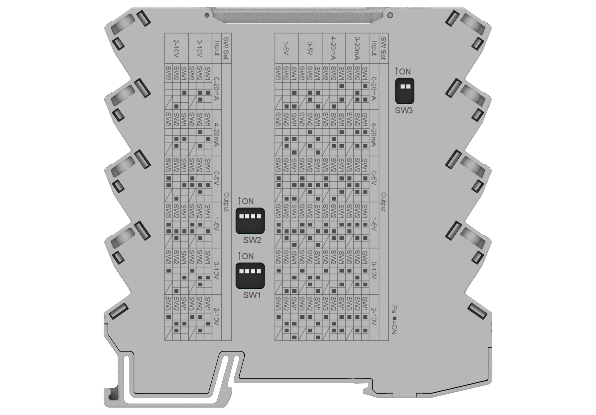 BM800 Ultra-Thin Signal Conditioner for PLC SystemsWith a 6.2mm profile, the BM800 saves panel space and configures via DIP switch. It isolates and converts signals, ensuring accurate transmission between field devices and PLC, enhancing system reliability.View Product →
Complete solutions typically include:
The relationship between power sensors and protection relays is covered in more detail in the article on how power sensors and protection relays prevent costly electrical failures. It is worth reading if you are building a complete protection scheme.
No, not reliably. AC coil relays have impedance characteristics designed for alternating current. Applying DC can hold the contact closed but may cause overheating or abnormal operation. Always select the relay for the exact coil voltage type.
The current rating depends on the contact configuration and contact material. A standard plug-in relay may rate from 5A to 15A at 120V AC. Always verify the datasheet and check the inrush capacity.
When the coil is driven by a DC controller, a flyback diode is recommended to dampen the reverse voltage spike when the output turns off. This protects the PLC or controller output from inductive kickback.
Use an auxiliary contact or a feedback loop. A signal conditioner can monitor the coil current or contact state remotely. This gives you visibility inside the control panel without opening the cabinet.
Choosing the right 24V to 120V relay is not about picking any relay with your voltage numbers in the datasheet. It is about matching the coil to the controller, the contacts to the load, and the mounting to your panel. Add a protection layer for critical circuits, and use a signal conditioner if you need remote feedback. With the right components, the control-to-load interface will run reliably for years.
If you are building a larger energy monitoring system, consider implementing an energy efficiency management platform alongside your switching infrastructure. This gives you both control and visibility into how much power your 120V circuits consume.


 Email: [email protected]
 Phone: +86-18702106858 / +86-21-69156352
No.253 Yulv Road, Jiading District, Shanghai, PRC 201801





