

 English
 Deutsch
News
Home / News / Industry News / How Power Sensors and Protection Relays Prevent Costly Electrical Failures
Every industrial electrical system depends on one quiet assumption: that the numbers reported by monitoring equipment reflect what is actually happening in the conductors. When that assumption breaks down, breakers trip for no visible reason, motors overheat undetected, and maintenance teams chase symptoms instead of causes. Accurate power sensors are the layer that keeps this assumption true, feeding current and voltage data into meters, controllers, and relays with enough precision to act before a fault becomes a failure.
Facility teams often discover the value of sensing accuracy only after an incident. A feeder that trips intermittently, a transformer that runs hotter than its nameplate suggests, or a billing dispute over an electricity energy meter reading are all downstream symptoms of upstream measurement gaps. This article walks through the core sensing technologies behind modern circuit protection, how they compare, and how they combine into a coherent monitoring architecture.
A split core current transformer is built with a hinged or separable core, allowing it to be installed around an existing conductor without disconnecting the circuit. This design advantage matters most in retrofit projects, where shutting down a feeder to install a solid core transformer is operationally expensive or impossible on critical loads.
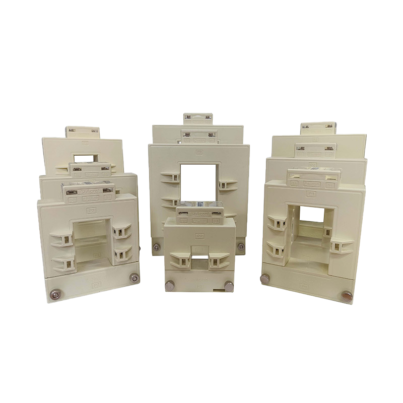
Accuracy class is the defining specification. Metering-grade transformers are typically built to class 0.2 or 0.5, meaning the reported current stays within that percentage of the true value across the rated range. Protection-grade transformers trade some of that precision for a wider dynamic range, since their job is to stay linear through fault-level currents rather than to bill accurately at normal load. Choosing the wrong class for the application is one of the most common design mistakes in secondary metering circuits.
| Accuracy Class | Typical Use | Error Limit at Rated Current |
|---|---|---|
| 0.2 | Revenue and precision metering | 0.2 percent |
| 0.5 | Commercial submetering | 0.5 percent |
| 1.0 | General industrial monitoring | 1.0 percent |
| 3.0 | Protection and indication | 3.0 percent |
Rogowski coils use an air-core winding instead of an iron core, which removes core saturation as a limiting factor. This lets the same flexible coil measure a small load current and a severe fault current without the nonlinear distortion that a saturated iron core would introduce. The coil itself outputs a voltage proportional to the rate of change of current, so it is paired with an integrator circuit that reconstructs the actual current waveform.
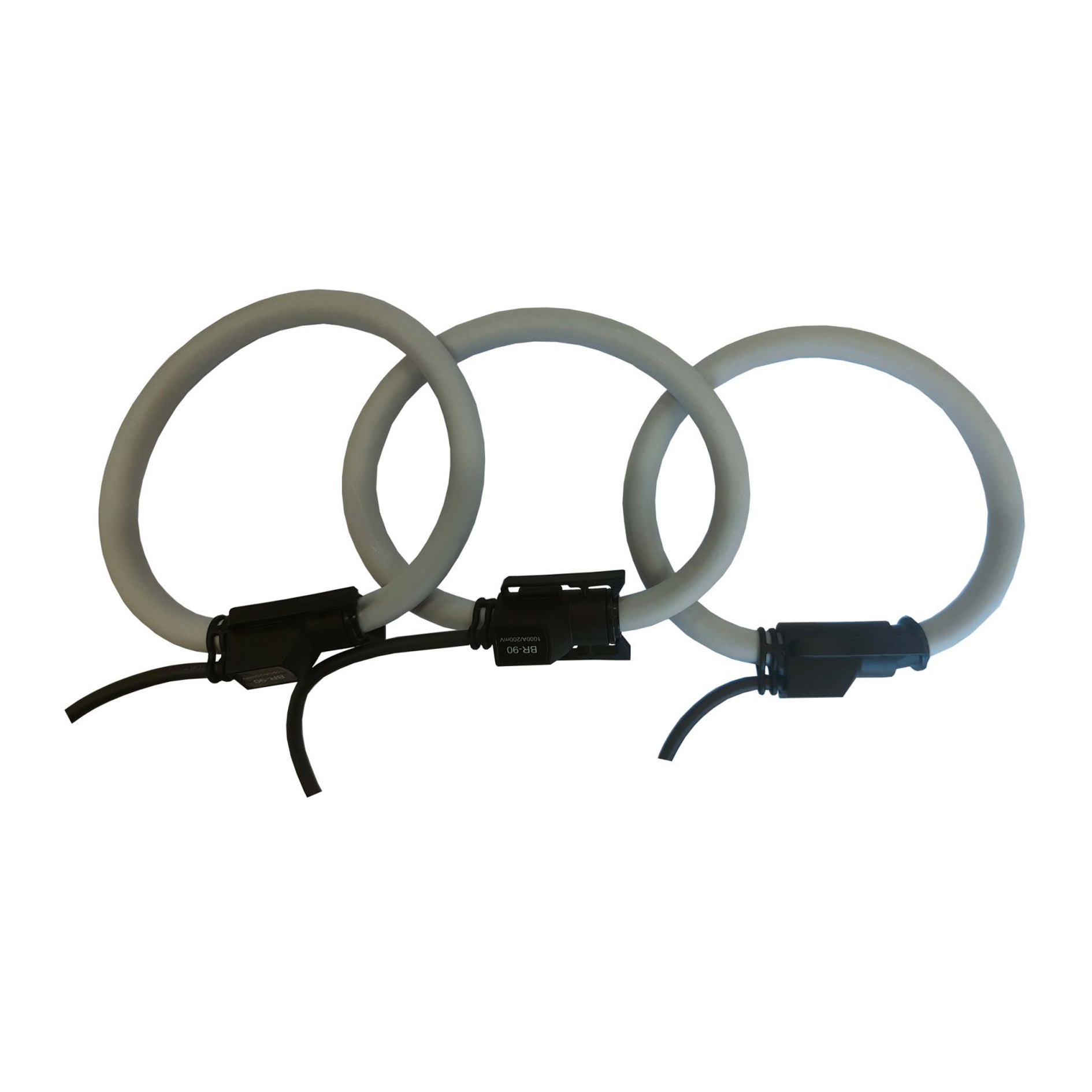
Because the coil has no iron core, it is lightweight and can be built as a flexible loop, making it practical to install around irregularly shaped busbars or in panels with limited clearance. The tradeoff is that the coil requires active signal conditioning to produce a usable output, unlike a passive current transformer that can drive a burden resistor directly.
Neither sensing method is universally better; each fits a different set of installation and accuracy constraints. The radar comparison below scores both technologies across five practical criteria on a relative scale, with a larger enclosed area indicating a stronger overall fit for that criterion set.
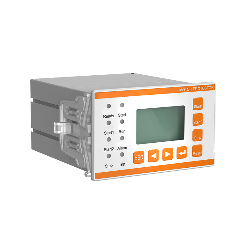
A motor protector continuously compares sensed current against a thermal model of the motor winding, rather than relying on a fixed instantaneous threshold. This distinction matters because a motor can safely carry short overload currents during startup, but the same current sustained for minutes would degrade insulation. Thermal modeling lets the protector distinguish between a normal starting transient and a developing overload condition.
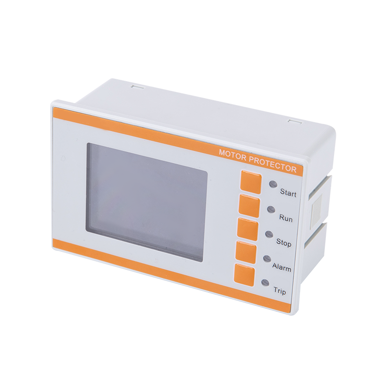
Common triggers built into a motor protector include phase loss, current imbalance between phases, locked rotor conditions, and cumulative thermal buildup. Each of these represents a distinct failure mode, and treating them separately allows maintenance teams to diagnose the actual root cause instead of resetting a generic trip and hoping the problem does not recur.
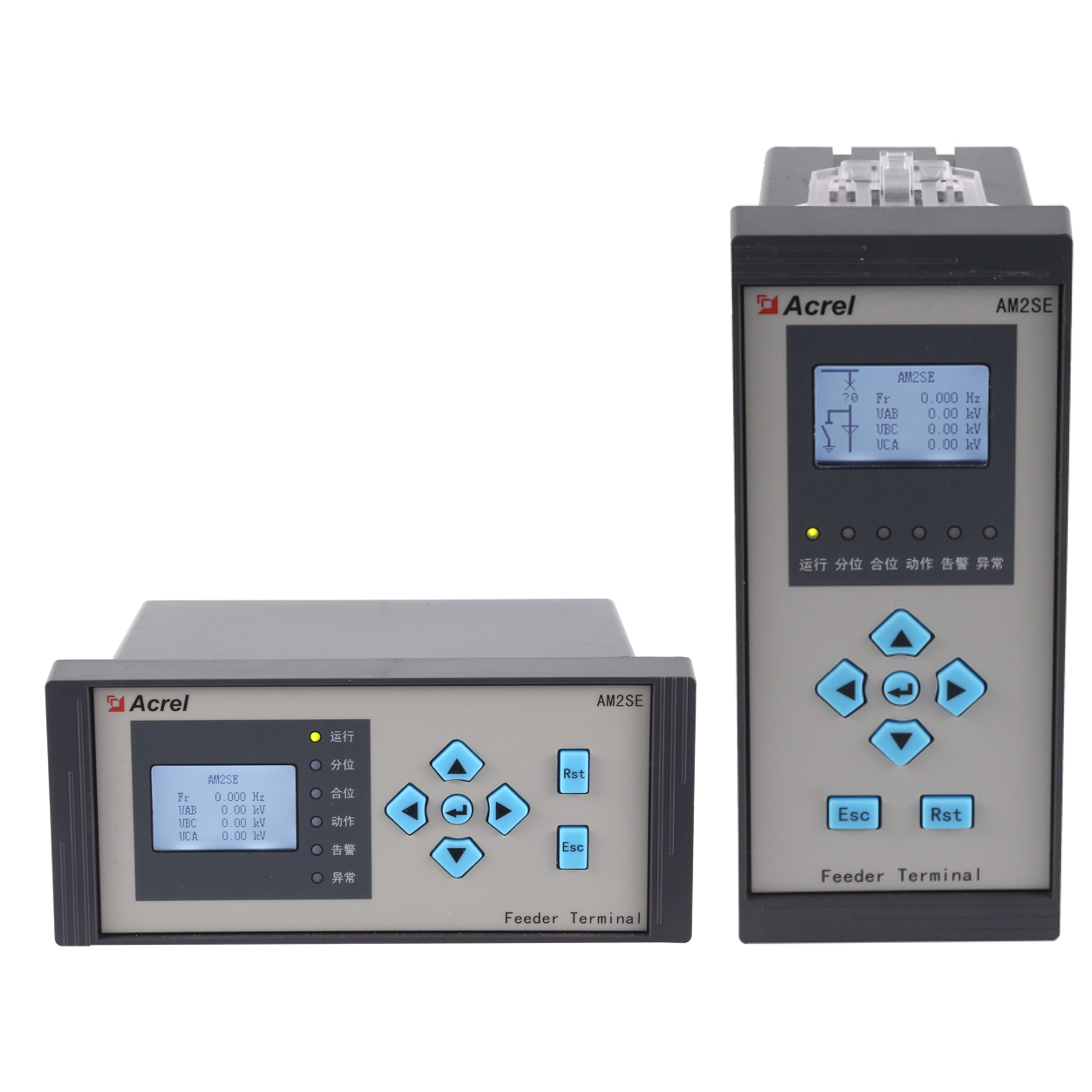
Where a motor protector focuses on a single load, a protection relay works at the feeder, transformer, or substation level, coordinating trip decisions across multiple devices so that only the closest breaker to a fault opens. This selective coordination, sometimes called discrimination, is what keeps a fault on one branch circuit from taking down an entire building.
Solid state relays and mechanical relays differ mainly in response time, contact life, and susceptibility to mechanical wear. A solid state design switches without moving contacts, giving faster and more repeatable response, while a mechanical relay is often preferred where galvanic isolation and simple field replacement matter more than switching speed.
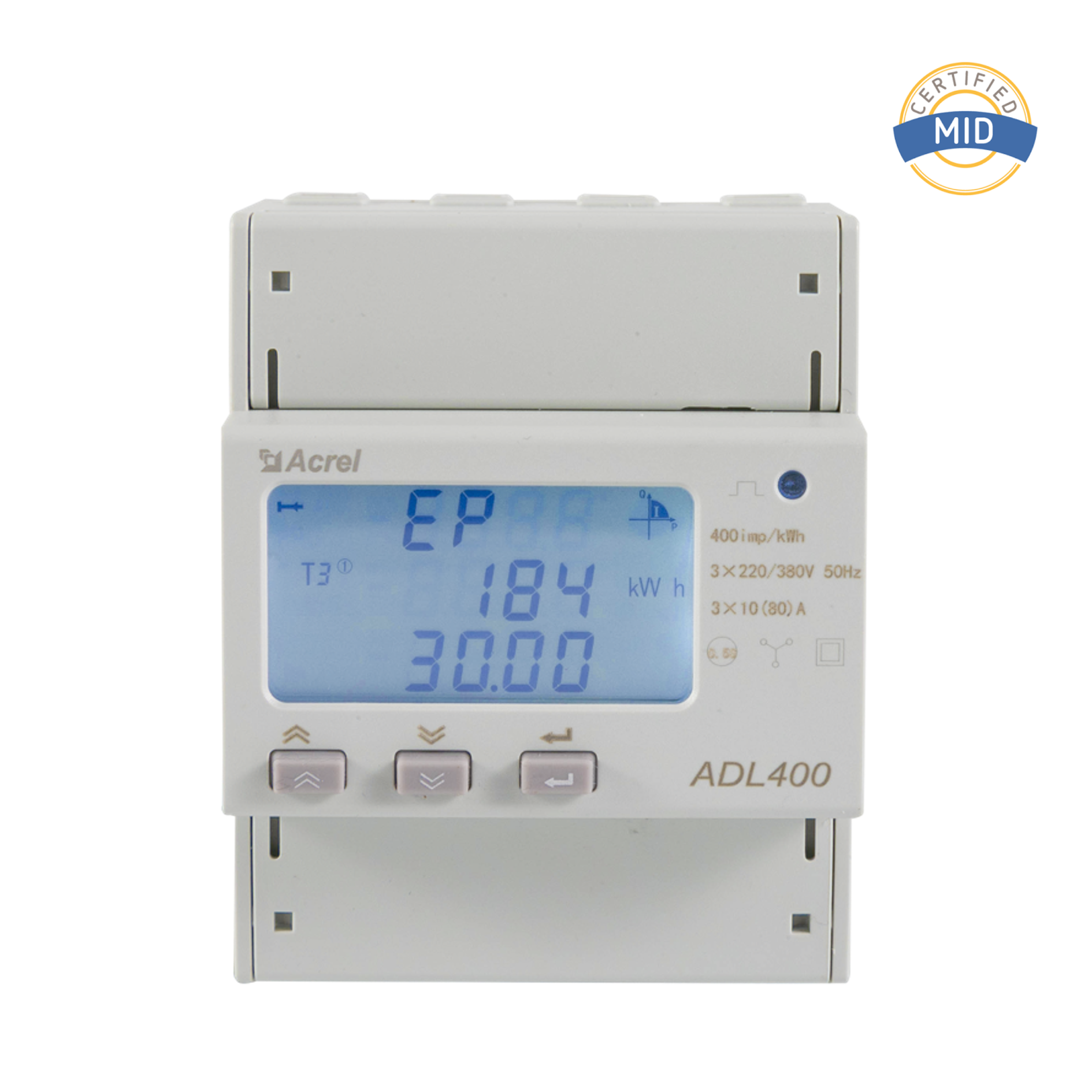
An energy meter with ct input relies entirely on the transformer or coil feeding it to preserve waveform fidelity, since the meter itself only digitizes and computes from what it receives. A digital electric energy meter connected to a poorly matched current transformer will still display readings, but those readings can carry a systematic offset that only shows up when compared against an independent check meter, often during a billing dispute or an energy audit.
Matching the transformer ratio and burden to the meter input range is a step that is easy to overlook during installation but expensive to correct afterward, since it usually means re-terminating live conductors. Facilities that plan submetering layouts around known transformer classes and burden ratings from the start avoid this rework almost entirely.
Most installations end up combining more than one sensing and protection technology rather than relying on a single device. A revenue metering panel might use a 0.2 class current transformer feeding a digital meter, while the same switchgear uses a lower accuracy protection-class transformer feeding a relay for fault clearing. Motor circuits typically pair a dedicated motor protector at the load with an upstream protection relay for backup coordination.
| Application | Preferred Sensor | Preferred Protection Device |
|---|---|---|
| Revenue billing metering | 0.2 or 0.5 class split core CT | Not applicable |
| Fault current detection | Rogowski coil or protection class CT | Protection relay |
| Motor overload monitoring | Split core CT sized to full load current | Motor protector |
| Retrofit submetering | Split core CT | Digital electric energy meter |
Documentation matters as much as hardware selection. Recording accuracy class, ratio, and burden for every installed transformer in a single register makes future troubleshooting faster and reduces the chance of a mismatched replacement part being installed during emergency maintenance.
Yes, that is the primary advantage of the split core design, though local electrical safety procedures for working near energized conductors still apply during installation.
The coil output is proportional to the rate of change of current rather than the current itself, so an integrator is required to reconstruct a usable current waveform for display or protection logic.
A motor protector is built around a thermal model specific to motor behavior, while a general protection relay coordinates trip decisions across a wider set of feeder and equipment conditions.
Not necessarily. Metering applications benefit from higher accuracy classes, but protection applications often prioritize linearity through high fault currents over precision at normal load.
The meter can only be as accurate as the signal it receives, so a mismatched ratio or burden on the transformer side will produce a consistent measurement error regardless of the meter internal precision.


 Email: [email protected]
 Phone: +86-18702106858 / +86-21-69156352
No.253 Yulv Road, Jiading District, Shanghai, PRC 201801





