

 English
 Deutsch
News
Home / News / Industry News / Protective Relays: Types, Operation, and Selection Guide for Power Systems
One faulty breaker, one overloaded feeder, one ground fault in the wrong place — that is all it takes to turn an ordinary operating day into a shutdown, an equipment failure, or a safety incident. A protective relay is the device that stops that escalation. It watches current, voltage, and frequency continuously, and when it sees a condition outside the expected envelope, it sends a trip command to the circuit breaker within milliseconds.
Choosing the right protective relay and setting it correctly determines whether your distribution system can isolate a fault quickly and precisely — before the fault becomes a much bigger problem. This guide explains how protective relays work, what types are available, and what actually matters when you evaluate a relay for a commercial, industrial, or utility installation. It also points to practical examples from Acrel's protection product line, keeping the selection process grounded in real hardware rather than theory.
At its core, a protective relay is a sensing device that compares the measured electrical quantities of a circuit against preset threshold values. When the measurement falls outside the acceptable range, it decides that a fault exists and energizes the trip coil of a circuit breaker. In that brief interval between detection and trip, the relay is the only component standing between the circuit and severe thermal or mechanical damage.
The relay continuously samples line current through current transformers (CTs) and, in some cases, voltage through potential transformers (PTs). It compares these values against the configured pickup thresholds. For example, a motor protection relay might have an overcurrent pickup set to 120 percent of rated full-load current, with a time delay that allows momentary starting inrush to pass without tripping.
Once a threshold is exceeded, the relay applies its logic — inverse-time curves, differential comparisons, or directional checks — to decide whether the condition represents a genuine fault or a transient event. When a fault is confirmed, the relay closes its output contact to energize the breaker trip circuit. The entire sequence, from fault onset to breaker opening, often completes in 20 to 100 milliseconds, limiting the energy released into the failed equipment.
After the breaker opens, the relay either resets automatically or remains latched until an operator acknowledges the event. Numerical relays also record fault current values, trip times, and waveform data. This event log is invaluable during commissioning and maintenance. Proper coordination with upstream and downstream devices — often set through time-current curves — ensures that only the breaker closest to the fault opens, preserving service in the rest of the system.
Protective relays can be grouped by construction technology or by function. For most purchasers, the functional classification matters more because it directly maps to the application.
| Relay Type | Primary Function | Typical Application | Key Advantage |
|---|---|---|---|
| Overcurrent | Trips when current exceeds a set value | Feeder, motor, transformer protection | Simple, economical, and widely available |
| Differential | Compares current entering and leaving a protected zone | Transformer, busbar, generator protection | High sensitivity to internal faults |
| Distance | Measures impedance to locate the fault point | Transmission and sub-transmission lines | Works reliably across long line sections |
| Directional | Checks current direction in addition to magnitude | Ring mains, parallel feeders, distributed generation | Prevents unnecessary tripping during reverse-power flows |
Overcurrent relays are the most common type. They detect short-circuit currents and overload currents. The time-current characteristic can be instantaneous, definite-time, or inverse-time, which allows engineers to coordinate a cascade of relays from the source down to the final feeder.
Differential relays compare the current entering a transformer or busbar with the current leaving it. If the two do not match, a fault exists inside the protected zone. Distance relays, also known as impedance relays, are used on transmission lines where fault location is geographically distant from the relay point. They measure the ratio of voltage to current and estimate the distance to the fault.
The value of a protective relay becomes most obvious in systems where a fault can affect a large number of loads or where consequence of damage is high. The following are the most common deployment points.
In substations and distribution switchboards, relays protect transformers, incoming feeders, and busbar sections. A short circuit on a busbar can destroy the entire switchboard if the fault is not cleared quickly. Modern protection relays also provide remote monitoring and event storage, allowing operators to review system performance. Acrel combines protection and monitoring in this area, including substation and distribution wireless monitoring solutions that pair the AM2SE protection relay with wireless temperature sensors and gateways.
For substation and distribution panels, the Acrel AM2SE protection relay provides overcurrent, earth-fault, and temperature monitoring in a compact DIN-rail package, making it suitable for MV switchgear and LV distribution cabinets where space is limited and connection simplicity matters.
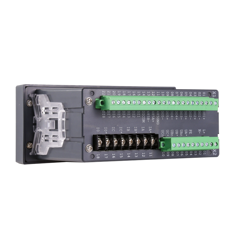 Medium Voltage Protection Relay for Ring Main UnitsThe AM2SE relay offers modular protection for 10kV switchgear, with programmable inputs, ANSI functions, fault recording, and versatile communication options for efficient integration.View Product →
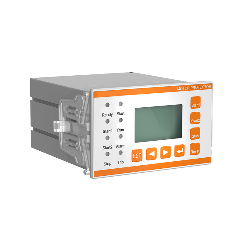
Motors are especially vulnerable to overload, phase loss, and leakage currents. A circuit breaker alone does not detect those conditions. A dedicated motor protector monitors the current draw and provides a trip before the winding insulation degrades. Acrel's ARD2M motor protector with leakage protection and event recording is designed for AC motor circuits up to 690 V, with programmable trip parameters and event logs for troubleshooting.
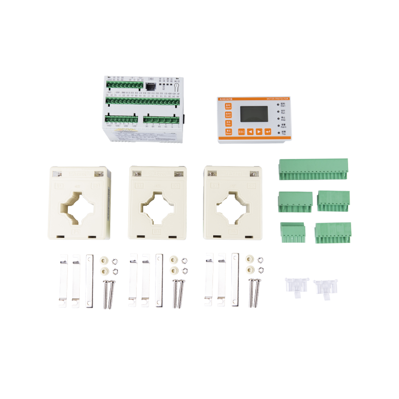 Low Voltage Motor Protector with Leakage and Event RecordingDesigned for AC motors up to 690V, this protector monitors overload, phase loss, and leakage, with programmable I/O and event logs to aid troubleshooting.View Product →
Feeder protection clears faults on lines connected to a switchboard, limiting the damage to the faulted circuit. Busbar protection is more complex because a busbar fault is often accompanied by high current from multiple sources. Differential protection schemes are the standard solution for high-voltage busbars, while low-voltage switchboards often rely on short-time overcurrent and instantaneous trip settings.
Selecting a protective relay is not simply a matter of picking a model that has the right nominal current rating. The following considerations determine whether the relay behaves correctly in your system.
A useful comparison for an electrical contractor is to think about the cost of a trip caused by a wrongly selected relay. If a relay trips too early, it can stop a production line unnecessarily. If a relay trips too late, it can allow equipment damage. The right selection balances both risks.
A protection relay is not a commodity product. It is safety-critical hardware. The manufacturer's ability to document, certify, and support the device over its service life is as important as the relay's own specification.
Acrel has built its energy management portfolio around the "cloud-edge-device" architecture, combining metering, protection, and communication hardware. The company reports over 600 patents and software copyrights and thousands of deployed system solutions across multiple countries. For facilities that need to integrate protection with energy efficiency management, Acrel's relays and gateways provide a practical path from individual breaker panels to a unified monitoring platform.
When you evaluate a supplier, ask about emergency response, firmware updates, and whether the relay's events can be exported into your existing maintenance software. If the vendor cannot explain how the relay will be commissioned and maintained, the relay is not ready for your switchboard.
An overcurrent relay monitors phase current and trips when it exceeds the setting. A ground fault relay measures residual current — the vector sum of the three phase currents — and trips when that sum indicates current is leaking to ground. Ground fault relays are typically more sensitive and protect against direct contact or insulation failures.
Yes. A circuit breaker protects the cable primarily against short-circuit current. It does not protect the motor windings against overload, phase loss, or long-term over-temperature. A motor protector adds those functions and can also provide leakage protection, which is especially valuable in wet or dust-laden environments.
Common practice is to test protection relays annually, or after any significant fault, or when the protection coordination is changed or the power system is modified. Secondary injection testing verifies the pickup setting, time-current curve, and trip circuit integrity. Numerical relays can be tested more quickly because their settings are stored digitally.
IEC 60255 is the key international standard for measuring and monitoring relays. Additional certifications such as CE, UKCA, or UL are required for equipment placed on certain regional markets. For motor protection, IEC 60947-4-1 also applies to the coordination between motor starters and protection devices.


 Email: [email protected]
 Phone: +86-18702106858 / +86-21-69156352
No.253 Yulv Road, Jiading District, Shanghai, PRC 201801





