

 English
 Deutsch
News
Home / News / Industry News / Current Transformer Troubleshooting: Common CT Faults and Effective Fixes
When a current transformer (CT) begins to under-report, overheat, or cause relays to trip at the wrong time, the most effective response is to stop replacing parts and start isolating the circuit. This current transformer troubleshooting guide is arranged the way a field engineer would actually work: start with the most dangerous condition, then move from electrical checks to mechanical and environmental causes.
In my experience with low-voltage and medium-voltage CT installations, the majority of faults come from a short list of avoidable mistakes. The sections below explain how to identify each one, what the symptom looks like, and what to fix before declaring the CT defective.
The most dangerous CT condition is an open secondary circuit. A CT is a current source; if the secondary cannot deliver current, the magnetic flux in the core rises until the secondary voltage jumps to a level that can punch through insulation. The result is an electric shock hazard, an overheated CT, and often permanent damage to the winding.
Check every connection from the CT terminals to the meter or relay. Look for discolored terminal blocks, loose screws, a test switch in the wrong position, or a fuse that has blown in the secondary loop. Use a voltmeter in millivolt AC mode across the open secondary; a high reading confirms that the CT is trying to push current through an open circuit.
If the CT case is warm and the measured secondary current is zero, short the secondary winding immediately, then open the circuit at the meter end.
Burden is the total impedance connected to the CT secondary winding. It includes the resistance of the secondary wire, the meter current coil, relay burden, and terminal connections. Each CT has a rated burden, usually expressed in VA, such as 2.5 VA, 5 VA, or 10 VA. When the connected burden exceeds the rated burden, the CT saturates earlier and produces secondary current lower than expected.
The first clue is often that readings are accurate at low load but fall off as primary current increases. The fix is to reduce burden by using shorter and thicker secondary cables, selecting a 1A secondary CT instead of 5A for long cable runs, or replacing instruments with lower VA consumption. Calculate the burden before installation instead of waiting for readings to go wrong.
Reversed polarity is common when a CT is retrofitted into an existing panel. If the secondary leads are swapped, the CT output is phase-shifted by 180 degrees. The meter may display negative kWh, a reversed power factor, or the wrong direction of real power flow. On protection relays, reversed polarity can prevent fault detection.
Check the CT P1 and P2 markings or arrow direction and match the secondary terminals to the meter wiring diagram. A quick polarity test using a 1.5V battery and a sensitive DC voltmeter can confirm whether the CT is connected correctly. Also check that all three phases are wired in the same sequence; swapping two phase CTs produces distorted three-phase readings even if each CT is correct.
Every CT has a defined rated primary current and an accuracy limit. If the primary current exceeds this rating, the magnetic core saturates. The secondary output no longer follows the primary current linearly, so metering becomes inaccurate and protection elements may operate at the wrong time. DC offset from motor starts, asymmetric faults, and high inrush currents can also drive a CT into saturation.
For revenue metering, choose a CT with a primary rating at least 1.2 times the expected maximum continuous load. If you need a wide measurement range, consider a CT with a higher rating factor. For protection applications, use a CT with a specified accuracy limit factor, such as 5P10 or 10P20, rather than a metering-class CT.
Insulation failures on a CT are less common but more serious. Moisture, dust, mechanical damage, and heat can degrade the insulation between the primary and secondary windings, or between the secondary and ground. Check insulation resistance with a 500V or 1000V megohm insulation tester after the CT is isolated and discharged. A healthy low-voltage CT typically measures in the hundreds of megohms, but always confirm against the manufacturer minimum.
Ground the secondary circuit at one point only. Multiple grounds create unintended loops that can introduce current and cause false readings. If the CT feeds a revenue meter, confirm that the ground connection is on the proper side of the meter and that the shorting block does not defeat the ground.
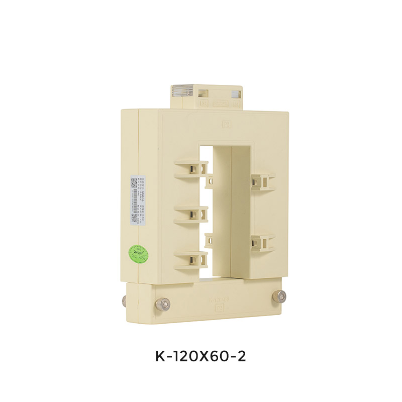
Split-core CTs are the go-to choice for retrofit work because they open and clip around an existing conductor without de-energizing the busbar or cable. But their accuracy depends on the mating surfaces being clean and fully closed. Dirty surfaces, a gap left by a foreign object, or over-tightening the bolt can create an air gap that increases error. Make sure the conductor passes through the center of the aperture and that the CT is not installed over two conductors unless it is designed for that purpose.
Knowing how a CT is constructed internally helps you understand why gaps and core alignment matter. For new live-circuit installations, a correctly fitted split-core CT remains a reliable and practical choice.
 AKH-0.66/K Split-Core Current Transformer for Retrofit ProjectsThis split-core CT enables easy installation on live circuits without removing the primary bus, ideal for power grid upgrades and renovation projects where continuity is essential.View Product →
When a fault is suspected, these six tests give a complete picture. Most can be performed with a small primary injection set, a multimeter, a megohm insulation tester, and a DC source.
Perform these tests when the CT is isolated and de-energized. After any maintenance, close all shorting devices before re-energizing.
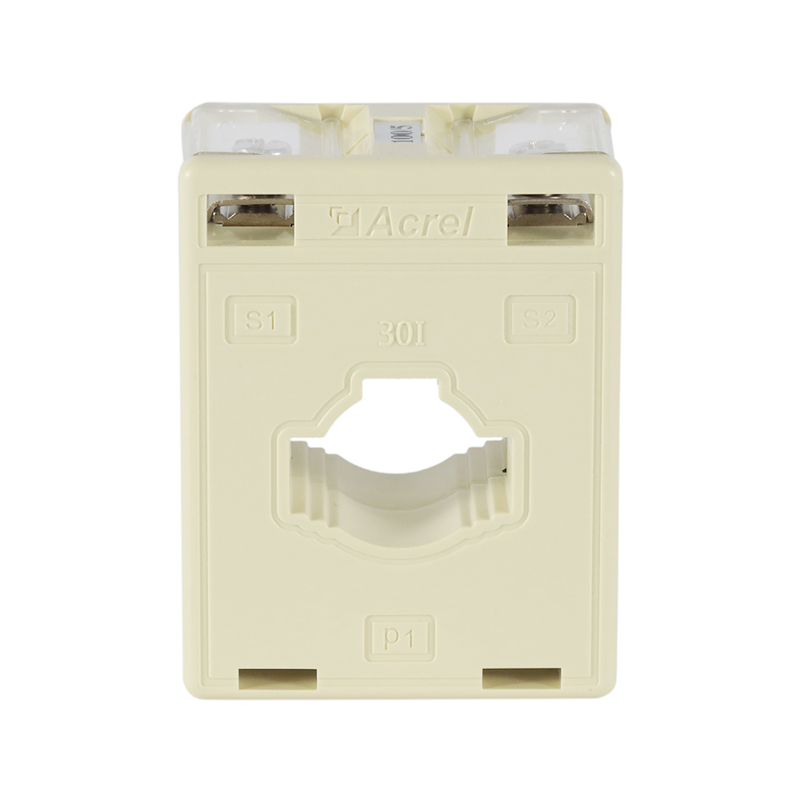
Prevention is cheaper than troubleshooting. Start with the right CT for the application: rated primary current above the maximum continuous load, accuracy class suited to the meter, and a rated burden higher than the calculated secondary load. If conductors are long or current is low, select a 1A secondary CT. For busbar installations where the circuit can be disconnected, a solid-core design generally gives the most stable performance. For existing live circuits, a quality split-core CT is acceptable if you verify that the mating surfaces close fully.
During installation, torque terminal screws to the manufacturer specification, do not overtighten, and always run a sanity check with a clamp meter after energizing the circuit. The same discipline that goes into a well-planned energy monitoring installation will save hours of troubleshooting later.
 AKH-0.66/I Solid-Core Current Transformer with High AccuracyA solid-core CT with Class 0.5 accuracy, designed for new construction. Its flip cover and flexible mounting options suit busbar or cable applications, supporting monitoring and protection.View Product →
CTs used in export installations may need CE, UKCA, or UL marks depending on the market. UL-listed split-core CTs are expected in many North American industrial and commercial panels. Certification status affects not only safety approval but also the documentation required for final inspection. Always confirm that the CT rating, marking, and certificate match the project specification before installation.
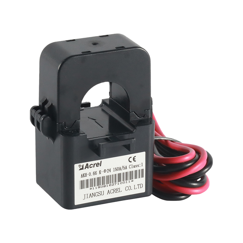 UL-Certified AKH-0.66/K-Φ Split-Core Current TransformerThis UL-certified split-core CT is reliable for export installations. It offers multiple output options and wide temperature range, suitable for maintenance and retrofit projects.View Product →
An open secondary circuit is the most likely cause. A CT with open secondary develops high core flux and heats rapidly. De-energize the primary, short the secondary, then inspect the secondary connections and shorting block.
Not for metering. If the primary current exceeds the CT rated primary current, the core saturates and the output becomes nonlinear. Select a CT with a primary rating above the maximum continuous load, again checking the rating factor if short-duration overloads are expected.
The most common explanation is reversed polarity on one or more CTs, or phase sequence wiring mismatch. Run a polarity test and verify that each CT secondary connects to the correct phase terminal on the meter.
High-voltage CTs typically follow a scheduled maintenance program, often every three to six years. Low-voltage CTs can be verified after initial installation, after nearby circuit changes, or whenever a metering anomaly appears.


 Email: [email protected]
 Phone: +86-18702106858 / +86-21-69156352
No.253 Yulv Road, Jiading District, Shanghai, PRC 201801





