

 English
 Deutsch
News
Home / News / Industry News / Current Sensing Relay 24V: Selection Guide, Wiring Tips & Applications
A commercial HVAC technician stands in a mechanical room staring at an air handler. The humidifier solenoid is wired through a 24V current sensing relay, and the solenoid will not engage. The blower motor is running and the relay should detect its current, but the contact stays open. A quick test with a clamp meter shows the blower is drawing 2.4A while the relay setpoint is 5A. The conclusion is simple: the relay is fine, but the setpoint is wrong.
A current sensing relay detects the flow of current in a conductor and switches an isolated control contact when that current crosses a user-defined threshold. The 24V in the name is the control voltage that powers the relay coil or electronics, not the current being monitored. Understanding this separation between the current-sensing circuit and the control circuit is the foundation for correct selection.
Every current sensing relay contains three sub-circuits inside one housing: the sensing element, the comparator, and the output contact.
The most common sensing element is a miniature current transformer (CT). The load conductor passes through the window of the CT. AC current in that conductor creates a magnetic field, and the CT produces a small secondary current proportional to the primary load current. A burden resistor inside the relay converts that current into a voltage the comparator can read.
The comparator continuously checks the measured signal against an adjustable reference, which is the setpoint. If the measured current exceeds the setpoint, the comparator output changes state. Many models also include hysteresis, a deliberate gap between the trip and reset values. Without hysteresis, a load that hovers near the setpoint would make the relay chatter by rapidly opening and closing the output contact.
The comparator energizes a relay coil that changes the state of an isolated output contact, available as normally open (N/O), normally closed (N/C), or changeover. The rating is usually in the range of 5A at 250V AC. The external control circuit a PLC input, a contactor coil, a solenoid, or an alarm is switched by this contact.
The 24V control power feeds the electronics and the output coil internally. Because the sensing circuit is galvanically isolated from the control circuit, you can safely use a 24V DC relay to monitor a conductor that carries several hundred amperes at a much higher voltage level.
Selecting a 24V current sensing relay is not about picking the first DIN-rail device with 24V in the description. The specifications below have the most influence on application success.
| Specification | Typical Range | Why It Matters |
|---|---|---|
| Control voltage | 24V AC/DC | Must match the existing control loop voltage |
| Sensing range | 0.1A to 200A | Determines the minimum and maximum current that can be detected |
| Setpoint accuracy | ±2% to ±5% | Affects trip precision at your target current |
| Hysteresis | 2% to 10% | Prevents chattering when load current is close to the setpoint |
| Contact rating | 5A / 250V AC | Must switch the connected load without welding |
| Response time | 50 ms to 500 ms | Determines whether the relay reacts to a fast fault or a slow trend |
| Mounting type | DIN rail, panel | Influences space planning and retrofit effort |
Rule of thumb: choose a sensing range where your expected normal current sits between 30% and 80% of the full-scale value. Below roughly 20%, CT-based sensors start to lose accuracy. Above 100%, you risk saturating the core and causing false resets.
A 24V current sensing relay is a universal interlock device. The most common applications fall into five categories.
In HVAC systems, the relay proves that a blower is actually moving air before energizing a humidifier solenoid, an electronic air cleaner, or a booster coil. The CT wraps around the blower motor feed. When the motor starts and draws current above the setpoint, the relay enables the 24V solenoid. If a belt breaks and the motor runs but current drops, the relay opens the solenoid circuit and protects the attached equipment from dry operation.
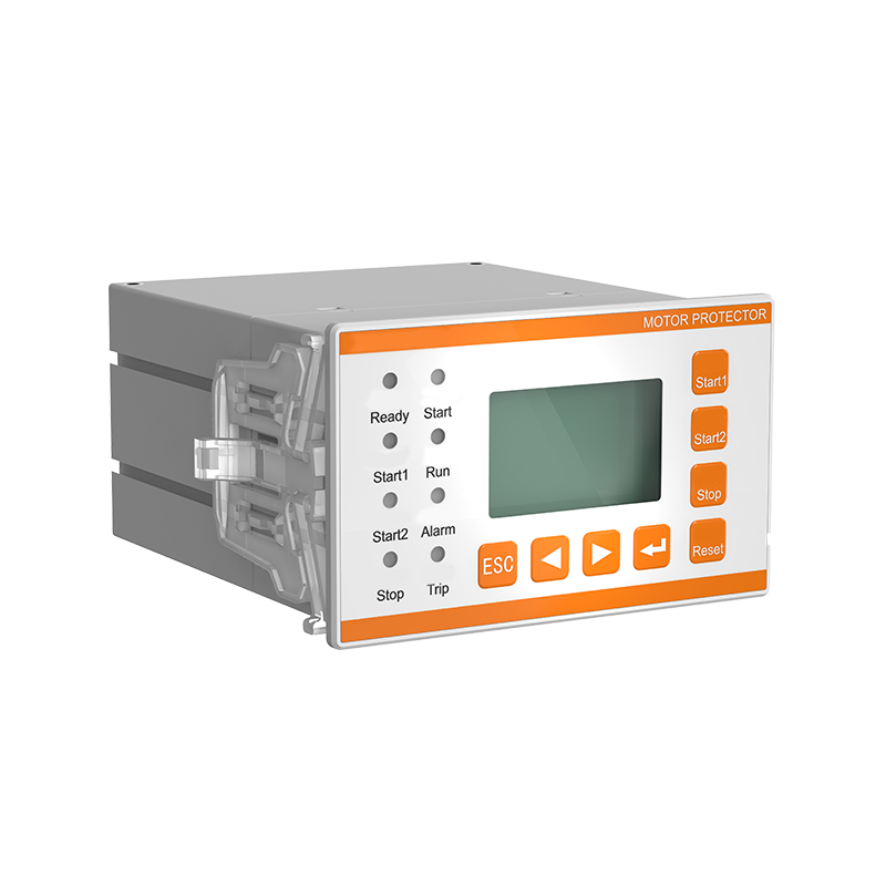
Motors draw predictable current during normal running. During an overload, current rises; during a phase loss, the remaining phases draw higher current. A current sensing relay watches these signatures and trips the contactor. For three-phase motors with additional needs such as leakage detection, an integrated device like the leakage protection motor protector with event recording combines current sensing, thermal monitoring, and trip-event logging in a single DIN-rail package.
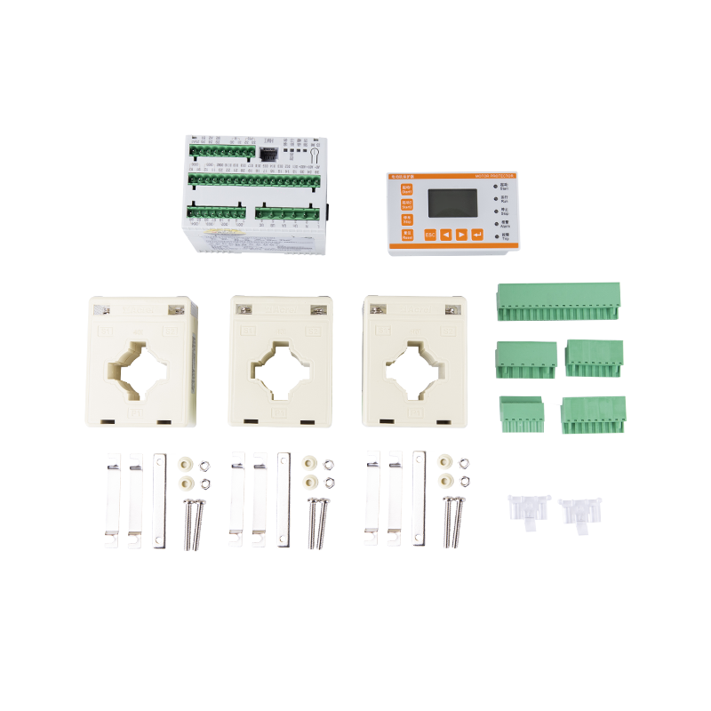 Leakage Protection Motor Protector with Event Recording for AC380V/690V MotorsThis Acrel ARD3M motor controller integrates leakage protection, event recording, and programmable I/O in a DIN-rail package, making it a comprehensive solution for low-voltage motor management and trip diagnostics.View Product →
Centrifugal pumps draw less current when the impeller spins in air instead of water. A current sensing relay configured as an undercurrent trip stops the pump before mechanical seals are damaged. This is a low-cost alternative to expensive dry-run guards.
In substation circuits, a more sophisticated protection relay like the AM2SE protection relay adds overcurrent, earth-fault, and temperature protection under one device that can feed data into an electricity distribution wireless monitoring system. For panels already using wireless temperature sensors, this relay is the second layer of electrical safety.
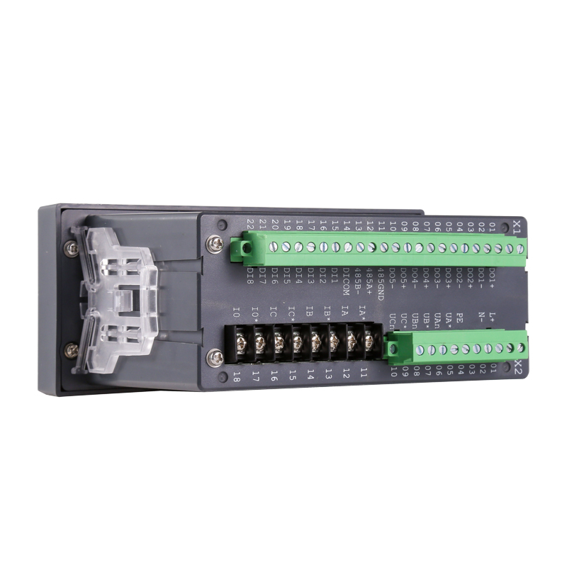 AM2SE Medium Voltage Protection Relay for 10kV Ring Main UnitsThe AM2SE relay offers ANSI-standard feeder protection, fault recording, and flexible communication for 10kV switchgear, providing essential safety and monitoring for medium voltage distribution systems.View Product →
Conveyor systems, mixers, and process heaters use current sensing relays to verify that a load is running before starting the next step in a sequence. In energy management projects, the relay output provides a simple dry contact signal that a gateway can pull into the energy efficiency management solution for visibility into equipment runtime and load conditions.
Correct installation matters more than product selection. A relay with the wrong CT orientation or a setpoint placed too close to the normal current will cause false trips in a production environment.
When retrofitting an existing panel, the load conductor is often already connected and power cannot be interrupted. In this case, a split core current transformer can be clamped around the conductor without disconnecting the load, which makes the retrofit significantly faster and safer.
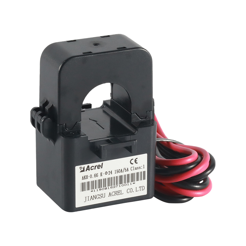 Split Core Current Transformer for Retrofits and Solar PV MonitoringClamp-on AKH-0.66 CTs allow current measurement without interrupting wiring, ideal for upgrading existing panels or integrating with solar inverters and energy management systems.View Product →
A current transformer is a passive sensing element; it only produces a proportional secondary current. A current sensing relay adds the comparator, the setpoint, and the switching contact in one package. The CT is the sensing part of the relay.
Most CT-based relays only work with AC current. DC current requires a Hall-effect sensor or a shunt-based measurement. Always check the datasheet for the AC/DC rating before ordering.
Motors have a high inrush current, often 6 to 8 times the running current. If the response time is too fast, the relay trips during startup. Increase the delay or set the setpoint above the inrush level.
Hysteresis is the gap between the trip point and the reset point. It prevents the relay from rapidly toggling when the current hovers near the setpoint. A hysteresis of 5% to 10% is practical for most applications.
A current sensing relay is a small component with a large influence on uptime. The most common failures setpoint drift, wrong CT range, or a mismatched contact rating are preventable with a few minutes of attention during selection and commissioning. When designing a 24V control loop that needs to know whether a load is actually drawing current, start with the sensing range, set the threshold at 120% of normal current, and integrate the output into your monitoring platform. That approach eliminates most false trips and protects the equipment you are paid to keep running.


 Email: [email protected]
 Phone: +86-18702106858 / +86-21-69156352
No.253 Yulv Road, Jiading District, Shanghai, PRC 201801





