What is the actual science behind smart meters? how
How Smart Meters Actually Work: The Physics and Engineering Behind Real-Time Energy Monitoring
Most people interact with a smart meter the same way they interact with a thermostat — they see the output, not the mechanism. But behind every kilowatt-hour reading, every demand spike alert, and every remote disconnect command lies a carefully engineered stack of physics, signal processing, and communication protocols. Understanding how smart meters work at a technical level is not just an academic exercise. It has direct implications for energy efficiency, system safety, billing accuracy, and the growing deployment of DC-based infrastructure worldwide.
This article unpacks the actual science behind smart meters — from the sensors that detect current and voltage to the algorithms that compute real power, reactive power, and energy totals. We also examine how the Multifunction DC Current Energy Meter fits into this picture, addressing the growing need for precision metering in solar PV systems, battery storage, EV charging stations, and data centers.
The Core Physics: What a Meter Is Actually Measuring
At its most fundamental level, an energy meter measures two things: voltage and current. Everything else — power, energy, power factor, harmonics — is computed from those two signals.
Voltage Measurement
Voltage is typically measured using a resistive voltage divider or, in high-voltage applications, a voltage transformer (VT). The divider scales the line voltage down to a safe, low-level signal that an analog-to-digital converter (ADC) can sample. In modern smart meters, this sampling occurs at rates of 4,000 to 16,000 samples per second, which is far above the 50/60 Hz power frequency. This high sampling rate allows the meter to capture not just the fundamental frequency but also higher-order harmonics.
Current Measurement
Current is more complex to measure because the conductor is live and cannot be interrupted. The two primary technologies used are:
Current Transformers (CTs): A toroidal coil wraps around the conductor. The changing magnetic field induces a proportional current in the secondary winding. CTs are highly accurate for AC circuits but do not work for DC.
Hall Effect Sensors / Shunt Resistors: For DC applications — including battery systems, solar panels, and EV chargers — a shunt resistor or Hall effect sensor is used instead. A shunt converts current to a small voltage drop (measured in millivolts), while a Hall effect sensor detects the magnetic field around a conductor without direct contact. Hall effect technology enables bidirectional DC measurement, a critical feature for systems with regenerative energy flows.
From Samples to Power: The Computation Layer
Once voltage and current waveforms are digitized, the meter's microprocessor performs digital signal processing (DSP) to calculate key electrical parameters. The instantaneous power at any moment is the product of the instantaneous voltage and current values. The meter then integrates these instantaneous power values over time to compute energy in watt-hours or kilowatt-hours.
For AC systems, real (active) power accounts for the phase difference between voltage and current. This phase angle, expressed as the power factor (PF), determines how much of the apparent power is actually doing useful work. A power factor of 1.0 means all power is active; a PF of 0.8 means 20% is reactive and does not contribute to useful energy delivery.
For DC systems, there is no reactive power by definition. DC current flows in one direction, voltage is nominally constant, and power is simply the product of DC voltage and DC current. This simplicity makes DC power measurement more straightforward in principle — but the engineering challenge lies in accuracy at low currents, bidirectional measurement, and noise immunity, all of which a multifunction DC current energy meter must address.
What Makes a Meter "Smart": Communication and Intelligence
The word "smart" in smart meter refers to two capabilities that traditional meters lack: bidirectional communication and on-board data processing.
Communication Protocols
Smart meters transmit data over a range of protocols depending on the application:
Protocol
Medium
Typical Use Case
RS-485 / Modbus RTU
Wired
Industrial panels, DIN rail meters
Modbus TCP / Ethernet
Wired (LAN)
Data centers, building automation
LoRaWAN
Wireless (long-range)
Remote outdoor installations
4G/5G LTE
Wireless (cellular)
Utility-grade smart metering
DLMS/COSEM
Standard data model
European utility metering standard
On-Board Intelligence
Modern smart meters embed microcontrollers or dedicated metering ICs (integrated circuits) that perform real-time computation. A typical metering IC handles:
Simultaneous sampling of multiple voltage and current channels
Harmonic analysis up to the 63rd harmonic in advanced models
Energy accumulation registers (import, export, net)
Demand calculation over configurable time windows (typically 15 or 30 minutes)
Tamper detection and event logging with timestamps
This on-board processing means the meter does not just pass raw data upstream — it delivers pre-computed, actionable parameters that energy management systems can act on immediately.
The Special Case of DC Metering: Why It Requires Different Science
As the energy landscape shifts toward renewables, battery storage, and direct current distribution, the limitations of traditional AC metering have become apparent. A conventional AC energy meter simply cannot measure DC circuits accurately. This is where the Multifunction DC Current Energy Meter becomes a critical instrument.
Why DC Measurement Is Fundamentally Different
In AC systems, current transformers exploit electromagnetic induction — which only works with changing (alternating) magnetic fields. DC current produces a constant magnetic field that a CT cannot detect. This is not a design shortcoming; it is a physical law. DC metering therefore relies on:
Shunt resistors: A precision low-resistance element placed in series with the circuit. The voltage drop across the shunt (measured in millivolts, typically 50 mV or 75 mV at full scale) is proportional to current. Accuracy depends on the shunt's temperature coefficient and long-term resistance stability.
Hall effect sensors: Based on the Hall effect — when current flows through a conductor in a magnetic field, a transverse voltage is generated perpendicular to both. Hall sensors can measure DC current without any direct electrical contact, enabling galvanic isolation and safe operation at high voltages.
Fluxgate sensors: Used in precision laboratory and industrial applications, fluxgate technology can measure DC currents to accuracy classes of 0.1% or better.
Bidirectional Energy Measurement
One of the defining features of a multifunction DC current energy meter is its ability to measure energy in both directions — import and export. This is essential in:
Battery energy storage systems (BESS): The battery alternately charges (import) and discharges (export). Accurate bidirectional metering tracks both flows separately for state-of-charge management and energy accounting.
Solar PV with storage: Panels generate DC power, batteries store it, and the system may deliver to an inverter or directly to DC loads. Each energy flow must be individually metered.
EV charging infrastructure: Vehicle-to-grid (V2G) systems allow EVs to return energy to the grid. DC meters in bidirectional charging stations must capture both the energy delivered to the vehicle and the energy returned from it.
A bidirectional DC meter maintains separate registers for positive (forward) and negative (reverse) energy accumulation. The difference between these registers gives the net energy — a critical figure for settlement, billing, and grid balancing.
Voltage Range and Safety Considerations
DC systems often operate at voltages that are dangerous or outside the range of AC meters. Modern multifunction DC energy meters are typically designed for voltage inputs of 0–1000 V DC or higher, covering:
Low-voltage BESS: 48 V, 96 V, 120 V DC bus
Commercial solar: 600–1000 V DC string or bus voltage
Data center HVDC: 380 V DC distribution
Telecom base stations: 48 V DC nominal
Safety standards for DC metering include IEC 62052-11 (general requirements), IEC 62053-31 (static meters for DC energy measurement), and regional standards that govern insulation, isolation, and surge withstand capability.
Multifunction Parameters: What the Meter Computes Beyond Simple kWh
A multifunction DC current energy meter is not just a kilowatt-hour counter. It is a real-time power quality and energy analysis instrument that continuously computes and logs a wide set of parameters.
Key Measured and Computed Parameters
Parameter
Unit
Application Relevance
DC Voltage (U)
V
Bus health monitoring, over/under voltage detection
DC Current (I)
A
Load monitoring, overcurrent protection
Active Power (P)
W / kW
Real-time load analysis
Forward Energy (Ep+)
kWh
Import accounting, billing
Reverse Energy (Ep-)
kWh
Export accounting, battery discharge tracking
Net Energy
kWh
Settlement, grid balancing
Maximum Demand
kW
Demand charge management
Temperature (optional)
deg C
Shunt temperature compensation, thermal monitoring
Accuracy Classes
Accuracy in energy metering is defined by IEC and ANSI standards. For DC energy meters:
Class 0.2S / 0.5S: Used in revenue-grade metering where billing accuracy is required. The "S" designation means the meter maintains its accuracy down to 1% of rated current, important for systems with wide load variation.
Class 1.0 / 2.0: Used in sub-metering and monitoring applications where billing is not primary. Suitable for energy management dashboards and operational monitoring.
A typical multifunction DC current energy meter in industrial applications achieves Class 0.5 accuracy for active energy and Class 0.2 for voltage and current measurement — meaning the measured value deviates by no more than 0.2% from the true value under reference conditions.
How Smart Meters Handle Harmonics and Noise in DC Systems
DC systems are not perfectly clean. Switch-mode power supplies, motor drives, inverters, and battery chargers all inject ripple and noise onto DC buses. A DC bus nominally rated at 48 V may have a peak-to-peak ripple of several volts at switching frequencies of 10–100 kHz. This ripple can introduce measurement error if the meter's ADC samples at the wrong moment.
Anti-Aliasing and Averaging
Smart meters address this through two techniques. First, an anti-aliasing filter at the ADC input removes frequency components above the Nyquist frequency (half the sampling rate), preventing high-frequency ripple from folding back into the measurement band. Second, the meter uses averaging over a fixed integration window (typically one second or one cycle of the dominant switching frequency) to smooth out short-term noise. The result is a stable, accurate reading of true average DC voltage and current even in electrically noisy environments.
Temperature Compensation
The resistance of a shunt resistor changes with temperature. A copper shunt has a temperature coefficient of resistance (TCR) of approximately 3,900 ppm per degree Celsius. Without compensation, a 30-degree rise in ambient temperature would introduce a measurement error of about 11.7%. High-accuracy DC meters incorporate an on-board temperature sensor and apply real-time temperature compensation to the shunt reading, maintaining accuracy across an operating range of typically -25 to +70 degrees Celsius.
Real-World Applications of Multifunction DC Current Energy Meters
Understanding the science is one thing; seeing it applied in real systems brings it to life. Here are four scenarios where the multifunction DC current energy meter delivers critical measurement capability.
1. Solar PV String Monitoring
A 1 MW rooftop solar installation may consist of 50 strings of 20 panels each, with each string operating at 600–900 V DC and delivering up to 10 A. Placing a DC energy meter on each string allows the energy management system to detect underperforming strings — a single shaded or degraded string delivering 15% less energy than its neighbors is immediately visible in the metering data. Without per-string metering, the performance gap is buried in aggregate inverter output data and may go undetected for months.
2. Battery Energy Storage State Monitoring
A commercial BESS with a 500 kWh usable capacity operates its battery pack at 800 V DC. The DC energy meter tracks cumulative charge (Ah) and energy (kWh) in and out of the battery over each charge/discharge cycle. By comparing integrated import and export energy over thousands of cycles, operators can calculate round-trip efficiency and detect degradation. A healthy lithium-ion system maintains round-trip efficiency above 92–95%; efficiency dropping below 88% is a signal for maintenance or capacity replacement.
3. EV Charging Station Revenue Metering
Fast DC charging stations (50 kW to 350 kW) deliver DC directly to the vehicle battery, bypassing the onboard charger. Revenue-grade metering at the DC output of the charging station ensures that the customer is billed for exactly the energy delivered to their vehicle — not the energy consumed by the charger's power electronics. The metering must satisfy local weights and measures regulations, requiring Class 0.5 or better accuracy with tamper-evident sealing and audit logging.
4. Data Center HVDC Distribution
Modern hyperscale data centers increasingly use 380 V DC distribution to server racks, eliminating one conversion stage compared to traditional AC UPS systems. Energy meters on each DC bus segment enable per-rack power usage effectiveness (PUE) monitoring. With average PUE targets below 1.3 for new data centers, granular DC metering at every power distribution unit (PDU) provides the data needed to identify and eliminate inefficiencies at rack level.
Integration with Energy Management Systems
A multifunction DC current energy meter does not operate in isolation. Its value multiplies when connected to an energy management system (EMS) or building automation system (BAS) that can aggregate, visualize, and act on the data.
Data Architecture
A typical deployment connects multiple meters via RS-485 Modbus RTU to a data concentrator or smart gateway. The gateway polls each meter at configurable intervals (typically every 1–15 seconds for operational monitoring, every 15 minutes for billing intervals) and forwards the data to a cloud or on-premise energy management platform. Modern meters support Modbus TCP over Ethernet directly, eliminating the concentrator for Ethernet-connected installations.
Alarms and Events
Smart meters support configurable threshold alarms. For a DC energy meter, typical alarm conditions include:
Overvoltage or undervoltage (e.g., bus voltage outside 90–110% of nominal)
Overcurrent (current exceeding rated capacity)
Reverse current unexpected in a unidirectional system (indicating a wiring fault)
Communication loss (meter offline for more than a configurable period)
Energy accumulation exceeding a daily or monthly threshold (cost management)
These alarms can trigger automated responses — shutting off a circuit breaker, sending an SMS or email notification, or flagging an anomaly in the EMS dashboard for operator review.
Historical Logging and Analysis
Many multifunction DC meters include internal data logging with flash memory capable of storing thousands of time-stamped event and load profile records. This onboard storage ensures that no data is lost even during temporary communication outages, and the logged data can be retrieved and analyzed once connectivity is restored.
Calibration, Drift, and Long-Term Accuracy
Smart meters are precision instruments, but they are subject to the same physical laws as all electronic equipment. Understanding drift and calibration requirements is important for anyone specifying or maintaining a metering installation.
Sources of Measurement Drift
Shunt resistance drift: Even precision manganin shunts exhibit slow resistance drift over years of thermal cycling. Annual calibration checks are recommended for revenue-grade applications.
ADC reference drift: The voltage reference used by the ADC sets the measurement scale. High-quality meters use bandgap voltage references with drift below 10 ppm per degree Celsius and long-term stability below 25 ppm per 1,000 hours.
Hall sensor offset: Hall sensors exhibit a zero-current offset voltage that drifts with temperature and aging. Auto-zero techniques — momentarily interrupting measurement to sample and subtract the offset — minimize this effect.
Calibration Standards
Revenue-grade DC energy meters are calibrated against certified reference standards traceable to national metrology institutes (NIST in the US, PTB in Germany, NIM in China). Calibration involves applying known DC voltage and current from a precision source and adjusting the meter's gain and offset registers to bring readings within the rated accuracy class. Meters in billing applications are typically recalibrated every 5 to 10 years, or whenever a significant maintenance intervention occurs.
Frequently Asked Questions
Q1: Can a standard AC smart meter be used to measure DC circuits?
No. AC meters rely on current transformers and AC-coupled signal paths that are incompatible with direct current. Attempting to use an AC meter on a DC circuit will produce incorrect readings and may damage the meter. A dedicated DC energy meter with shunt or Hall effect sensing is required.
Q2: What is the difference between a multifunction energy meter and a basic kWh meter?
A basic kWh meter records only cumulative energy consumption. A multifunction meter additionally measures instantaneous voltage, current, power, demand, and often harmonics. It supports alarm outputs, communication interfaces, and event logging — features that enable active energy management rather than passive billing.
Q3: How accurate does a DC energy meter need to be for EV charging billing?
Most jurisdictions require Class 0.5 or better accuracy for revenue metering at EV charging stations. Some regions (notably within the EU) require MID (Measuring Instruments Directive) certification, which mandates Class 1.0 or better and includes legal metrology requirements for tamper protection and audit trails.
Q4: What communication interface is most common for DC energy meters in industrial systems?
RS-485 with Modbus RTU is the most widely deployed wired interface in industrial and commercial energy metering. Ethernet with Modbus TCP is increasingly common in data centers and modern facilities. Wireless options (Wi-Fi, LoRa, 4G) are available for remote or retrofit applications.
Q5: How often should a DC energy meter be calibrated?
For sub-metering and monitoring applications, calibration every 5 years is typically sufficient. For revenue-grade applications (billing, grid settlement), annual verification and recalibration every 5 years is standard practice. Always follow the requirements of the applicable local metrological authority.
Q6: Can DC energy meters handle bidirectional current measurement?
Yes. Multifunction DC energy meters designed for battery storage or V2G applications measure current in both forward and reverse directions and maintain separate energy registers for each. This is a key differentiator from simpler unidirectional meters used in solar DC string monitoring.
Q7: What protection class should a DC energy meter have for outdoor installations?
Outdoor DC metering equipment should have a minimum IP54 rating for dust and water splash protection. In harsh environments (coastal, tropical, high-UV), IP65 or better is recommended. For panel-mounted meters in outdoor enclosures, the enclosure itself carries the IP rating and the meter can be IP20 or IP40.

 English
 Deutsch
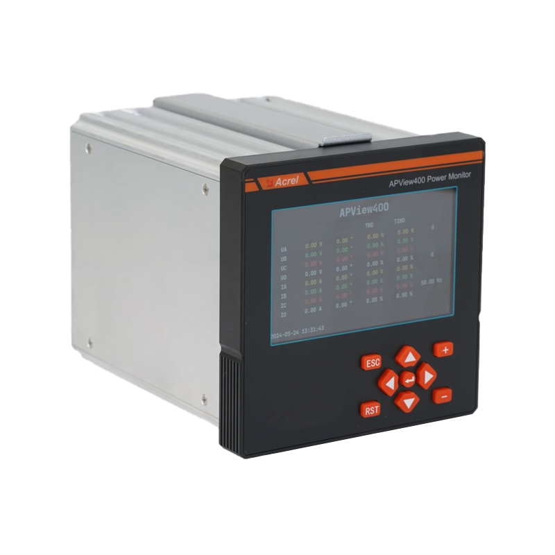 Part 1: Introduction 1.1 What is Power Quality and Why is it Important? In modern society, a stable ...View More
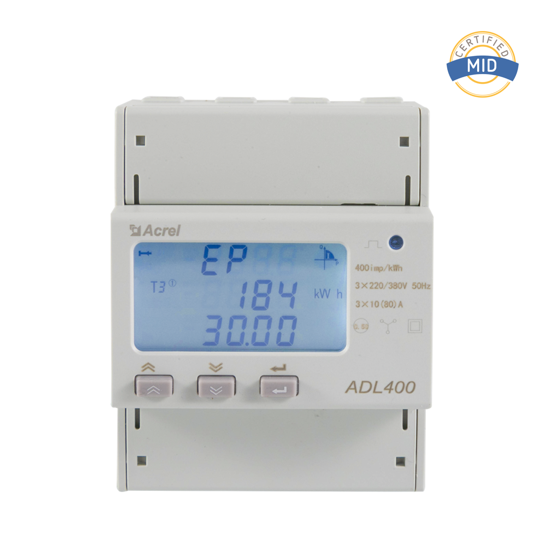 Introduction to AC Energy Meters In today’s rapidly evolving energy sector, accurate measurement and...View More
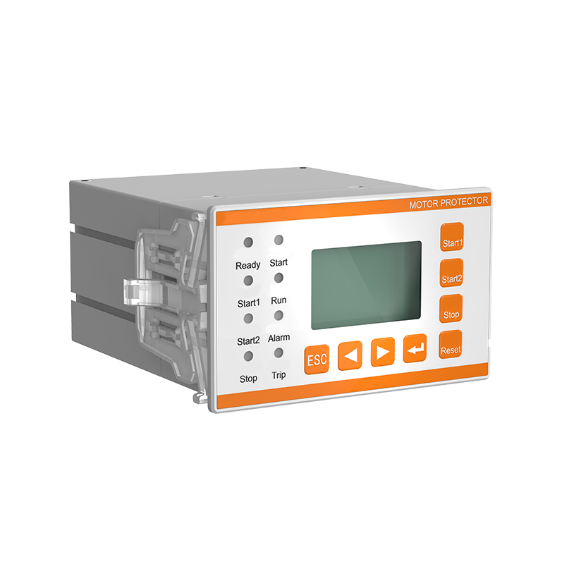 I. Introduction: The Critical Need for Motor Protection Electric motors are the undisputed workhorse...View More
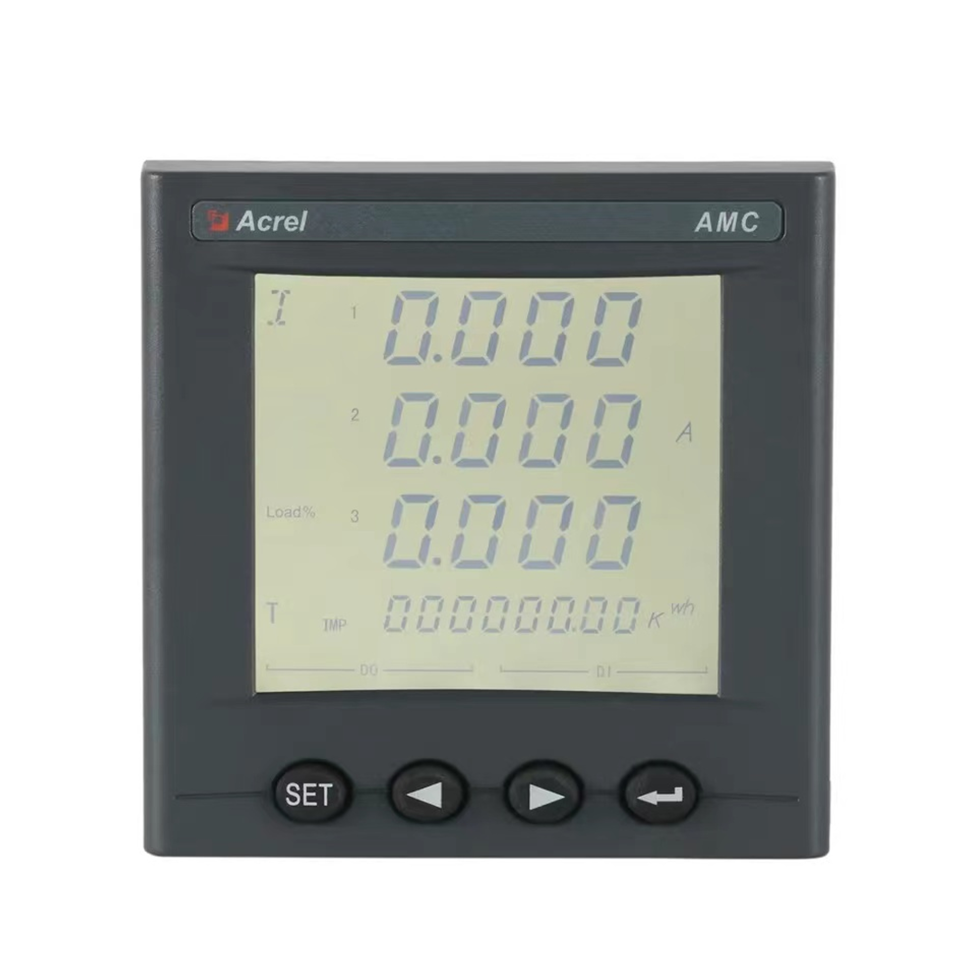 Introduction In modern industrial and commercial power environments, precise measurement and managem...View More
 Email: [email protected]
 Phone: +86-18702106858 / +86-21-69156352

