

 English
 Deutsch
News
Home / News / Industry News / How Modbus-Based Smart Gateways Turn Scattered Energy Meter Data Into Usable Power Insight
Most industrial sites did not set out to build a fragmented metering environment. It happened gradually: a panel builder installed one brand of meter for the main incomer, an electrical contractor added another for a new production line, and a retrofit project bolted on a third for lighting circuits. Each device speaks its own dialect of registers, baud rates, and addressing conventions. The result is a facility that generates enormous volumes of electrical data yet struggles to answer a simple question: where exactly is energy being consumed, and why.
This is the practical reason so many facility engineers converge on a single serial protocol for their metering layer. A well-configured smart gateway sits between field devices and upstream systems, translating RS485 traffic into Ethernet-based formats that building management platforms, SCADA layers, and cloud dashboards can consume without custom drivers for every meter model. Instead of maintaining a dozen point-to-point integrations, a plant standardizes on one addressing scheme and one polling logic, then lets the gateway handle the translation work.
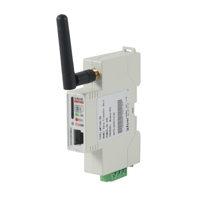
A gateway unit converting RS485 field traffic into Ethernet-based data streams
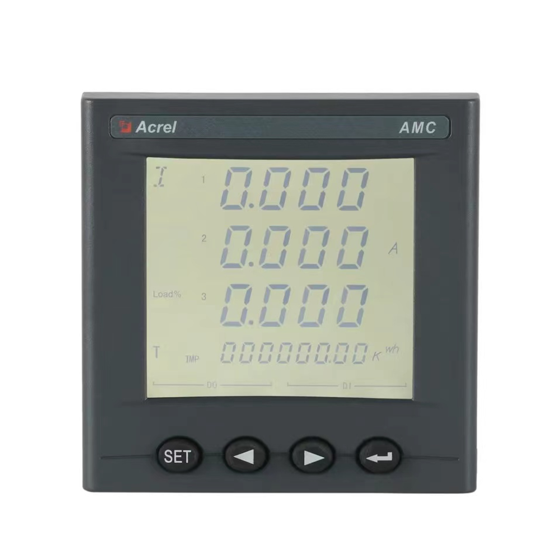
The underlying driver is cost of ownership. Facilities that rely on a mix of proprietary protocols report longer commissioning cycles and higher integration expense whenever a meter is replaced or a new circuit is added. A shared protocol layer reduces that friction because a modbus energy meter from any compliant vendor can, in principle, be added to the network using the same register logic already documented for the rest of the fleet.
Modbus RTU communication follows a master and slave model over a shared serial bus, typically wired as RS485. One master device, usually the gateway or a local controller, issues a request that includes a device address and a function code. Only the slave device matching that address responds, which keeps the bus deterministic even when dozens of meters share the same physical cable pair. Function codes define the operation: reading holding registers for measured values, reading input registers for status data, or writing single registers for configuration changes.
RS485 energy meter integration depends heavily on physical layer discipline. Wire polarity, daisy-chain topology instead of star wiring, and correct termination resistance at both ends of the bus all influence whether a meter responds reliably at longer distances or higher baud rates. Facilities that skip termination resistors often see intermittent timeouts that look like a software problem but are actually a wiring issue.
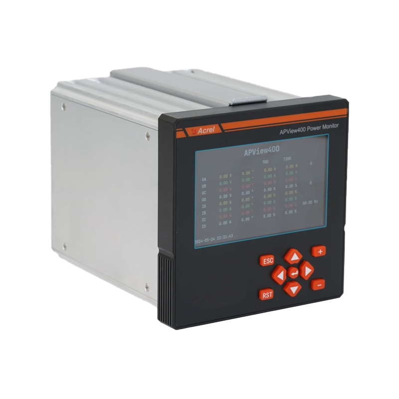
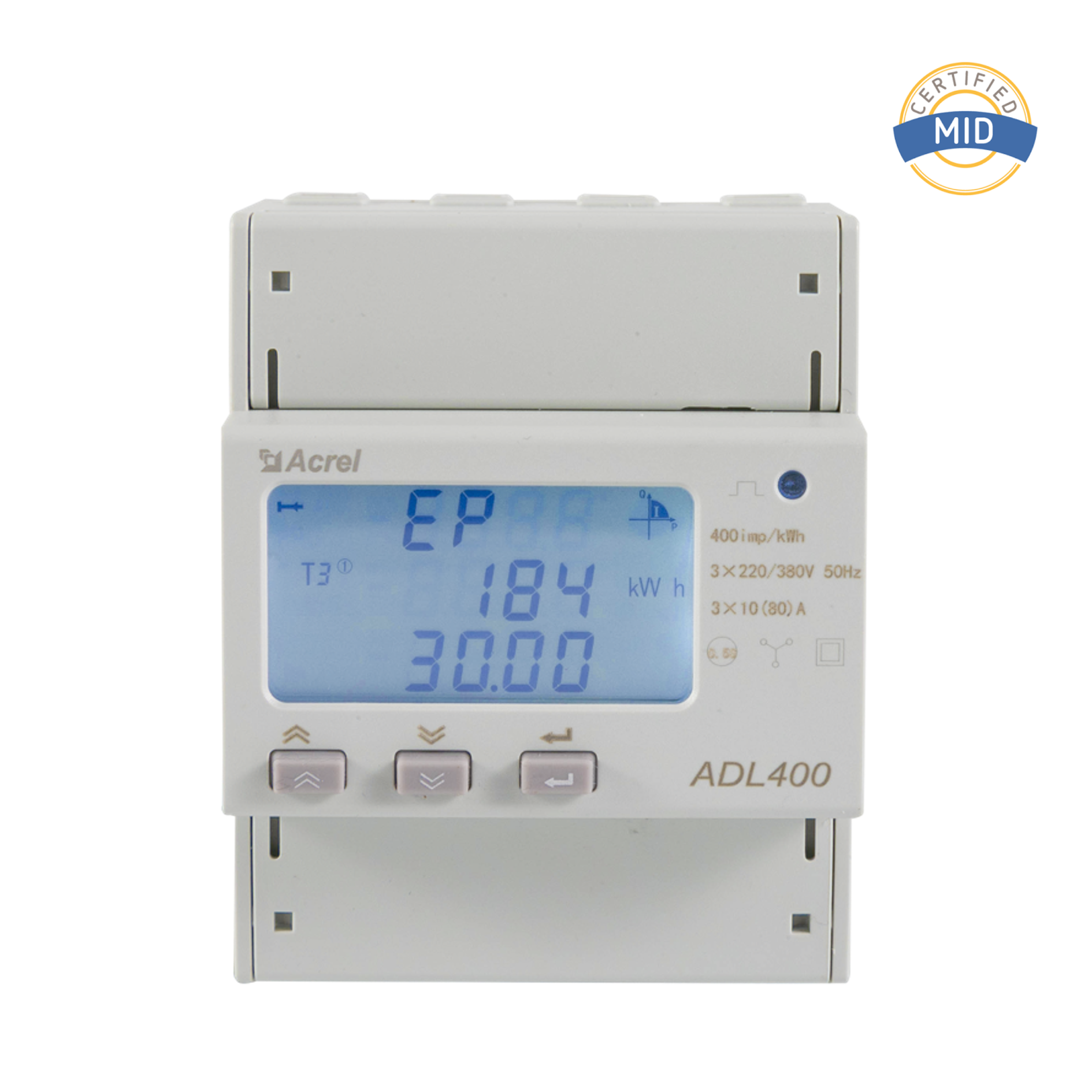
It helps to separate what each device type actually contributes before designing a network. A multi-circuits energy meter measures many feeders from a single unit, which suits panels with dozens of low-current circuits such as lighting or sub-metered tenant loads. A power quality analyzer goes further, capturing harmonics, voltage sags, flicker, and transient events that a basic energy meter typically does not record. The gateway does not measure anything itself; its job is aggregation and translation.
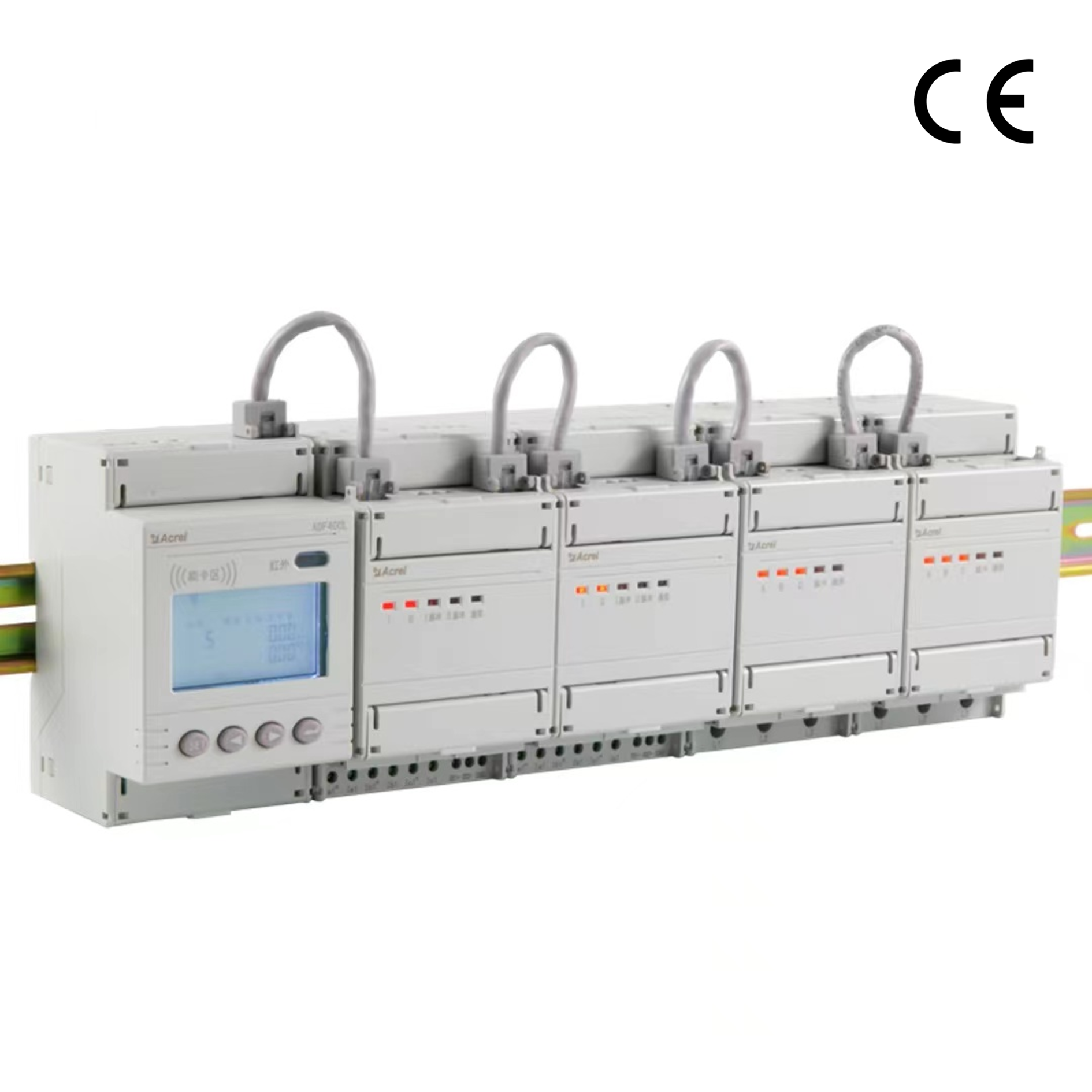
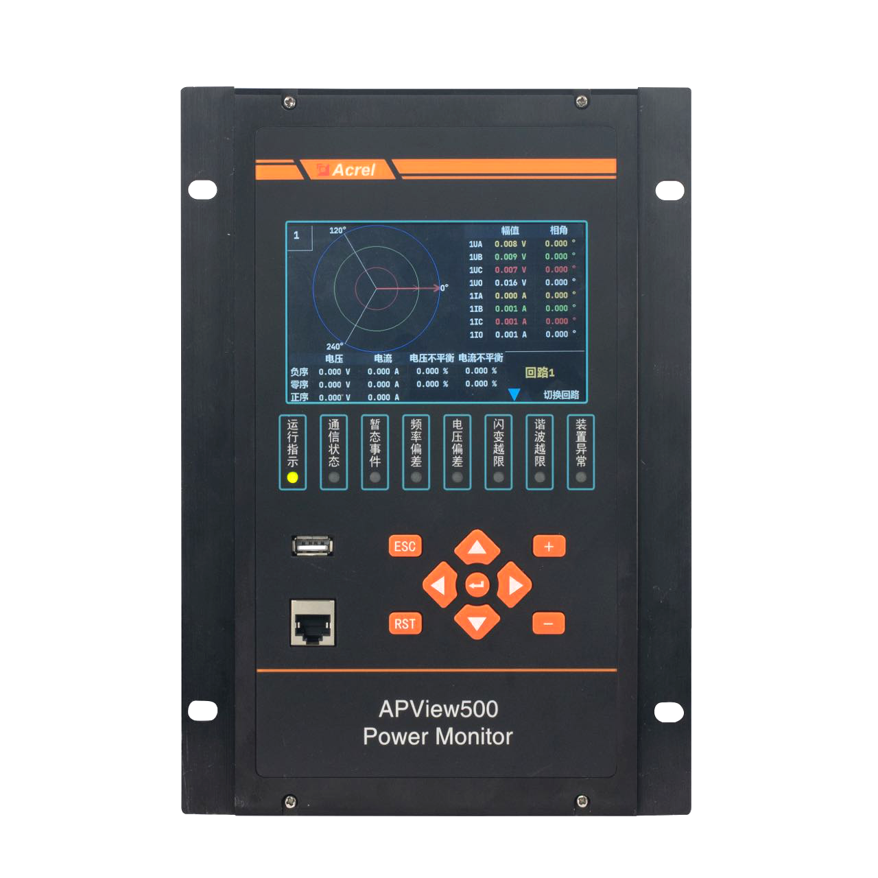
| Device Type | Primary Function | Typical Placement |
|---|---|---|
| Multi-Circuits Energy Meter | Sub-circuit consumption tracking | Distribution panels, tenant sub-metering |
| Power Quality Analyzer | Harmonics, sags, transients | Main incomers, sensitive load feeders |
| Smart Gateway (ANet series) | Protocol conversion, data aggregation | Communication room, network cabinet |
The ANet line of gateway hardware is frequently paired with meter fleets because it is designed around the same register conventions the meters already use, which shortens the mapping work described in the next section. Choosing devices designed to interoperate reduces the custom configuration that otherwise falls on the commissioning engineer.
Energy meter data mapping is the process of documenting which register address corresponds to which physical quantity, what data type it uses, and what scaling factor must be applied before the raw integer becomes a meaningful engineering value. Skipping this documentation is one of the most common reasons integration projects stall midway, because whoever configures the SCADA tags has to reverse-engineer the mapping from trial and error.
| Register Address | Parameter | Data Type | Scaling |
|---|---|---|---|
| 0x0000 | Phase A Voltage | Unsigned 16-bit | Divide by 10 |
| 0x0006 | Phase A Current | Unsigned 16-bit | Divide by 1000 |
| 0x000C | Total Active Power | Signed 32-bit | Divide by 100 |
| 0x0100 | Cumulative Energy | Unsigned 32-bit | Divide by 100 |
A useful discipline is to keep the register map version-controlled alongside the wiring diagram, so a technician replacing a failed meter years later does not have to guess at the original addressing scheme. Where possible, standardizing on the same map across every modbus energy meter in a fleet, even across different circuit sizes, means the same SCADA template can be reused rather than rebuilt for every panel.
Facility teams that move from isolated meter readouts to a gateway-aggregated network typically report two measurable effects: fewer discrepancies between billed and metered consumption, and a sharp drop in the manual effort spent reconciling readings across panels. The following figures summarize outcomes reported across different facility types after standardizing on RS485 energy meter integration with a common gateway layer.
Gateway configuration for power systems follows a predictable sequence, and skipping steps out of order is where most delays originate. The list below reflects the order most commissioning teams find effective.
Industrial protocol conversion becomes more complex once a facility mixes serial and Ethernet segments, because the gateway then has to manage two different timing models simultaneously. Underestimating polling latency on the serial side is a frequent cause of stale readings appearing on an otherwise correctly configured dashboard.
Some smaller installations still poll each meter directly from a local controller without a dedicated gateway layer. This works at a handful of devices but degrades as the fleet grows. The radar comparison below reflects how the two approaches compare across five practical dimensions.
Direct polling can outperform a gateway on raw latency for a very small device count, but that advantage disappears once a facility adds a second protocol, a redundant controller, or more than roughly fifteen meters on one bus.
Treating this checklist as a formal sign-off document, rather than an informal habit, is what separates commissioning projects that finish on schedule from those that reopen the same wiring closet three times.
Modbus RTU runs over a serial RS485 bus and is common at the meter level, while Modbus TCP runs over Ethernet and is typically used between the gateway and upstream systems. A gateway performs the conversion between the two.
Specifications often allow up to 32 devices per segment without repeaters, but practical reliability at longer polling frequencies is usually better maintained with fewer devices per segment, particularly on noisy industrial sites.
A power quality analyzer captures fast transient events and harmonic content that require higher sampling rates, so its register set and reporting frequency are structured differently from a meter focused only on cumulative energy.
Yes, as long as addressing, baud rate, and parity settings are aligned and each device's register map is documented separately, since register layouts are not standardized across manufacturers.
In most field reports, unterminated or improperly daisy-chained RS485 wiring is the leading cause, followed by polling intervals set too aggressively for the number of devices on the bus.


 Email: [email protected]
 Phone: +86-18702106858 / +86-21-69156352
No.253 Yulv Road, Jiading District, Shanghai, PRC 201801





