

 English
 Deutsch
News
Home / News / Industry News / How Does an Energy Meter Work: A Technical Breakdown of Principles and Functions
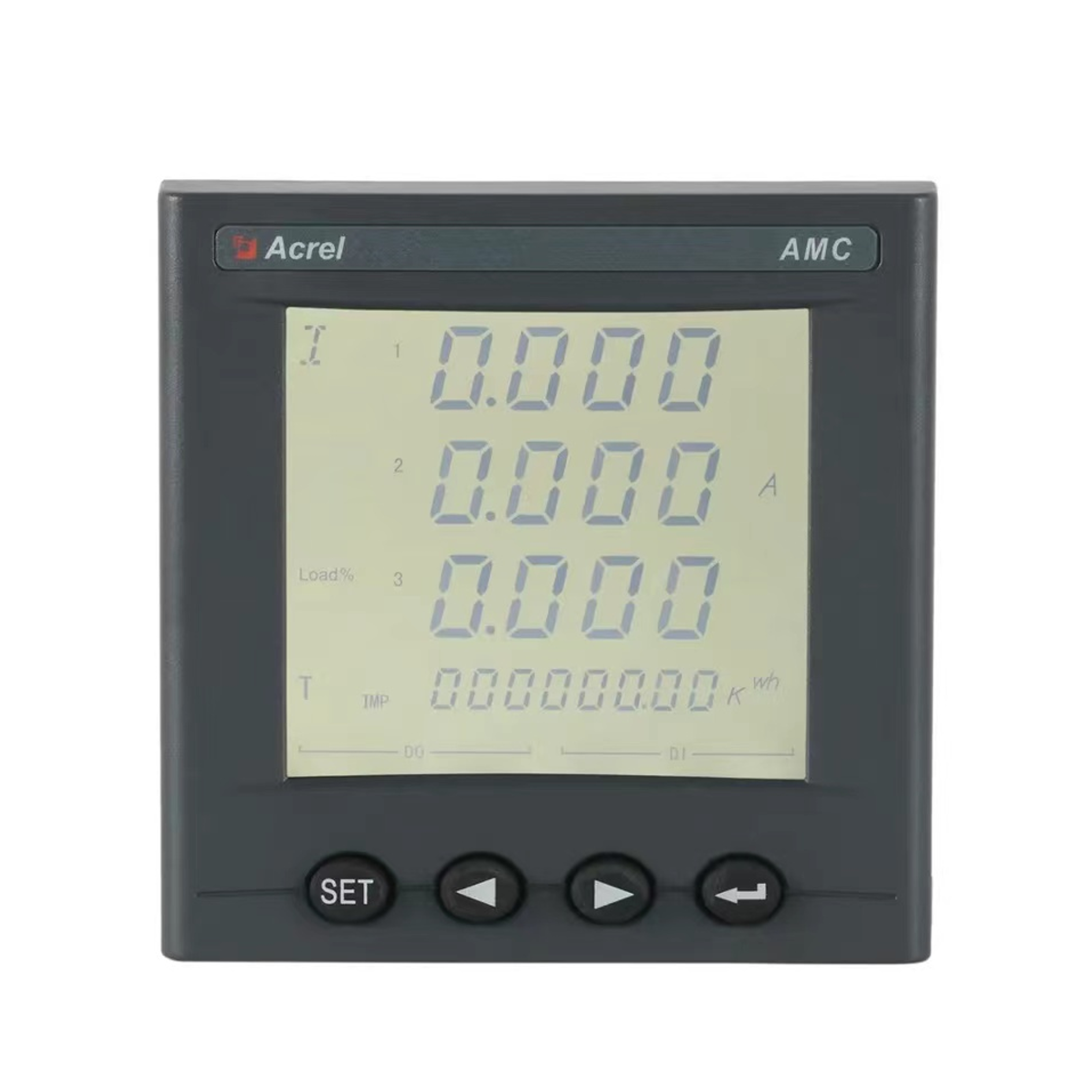
An energy meter is a measurement device installed at the point where electricity enters a building, a production line, or an individual circuit. Its job is straightforward on the surface but technically layered underneath: it continuously samples voltage and current, multiplies these values over time, and integrates the result into a usable unit of energy consumption, typically expressed in kilowatt-hours.
Unlike a simple current sensor, a properly designed meter accounts for the phase relationship between voltage and current. This distinction matters because loads such as motors, transformers, and switching power supplies draw current that is not perfectly aligned with voltage, which affects how much real work is actually being done versus how much current is simply circulating without producing useful output.
In practical terms, when someone asks how does an energy meter work, the honest answer involves three separate but connected tasks: sensing the electrical signal accurately, processing that signal into a meaningful energy value, and presenting or transmitting that value in a format that billing systems, facility managers, or automation platforms can use.
At the heart of every electric energy meter sits a sampling and calculation process. Modern meters rely on analog to digital conversion rather than the rotating disc method used in older mechanical designs. The general sequence looks like this:
This process runs continuously, which is why a meter can show both a real-time power figure and a running energy total without any manual reset. The accuracy of this entire chain depends heavily on how well the sensing components are calibrated and how stable the reference voltage inside the metering chip remains under temperature changes.
Field note: A meter that samples too slowly will miscalculate energy for loads with distorted current waveforms, such as variable frequency drives or LED lighting banks, because it misses the higher frequency components of the waveform.
A power energy meter is built from a small set of functional blocks, each responsible for one stage of the measurement chain. Understanding these blocks helps explain why two meters with similar specifications can still behave differently under real load conditions.
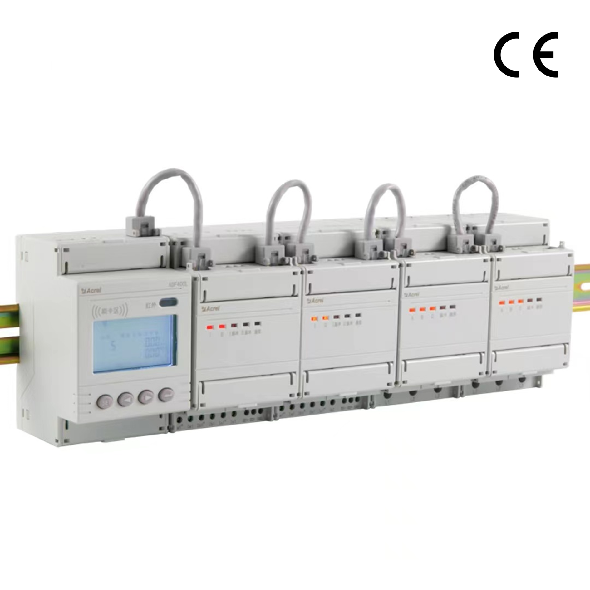
The diagram above illustrates a typical layout, where sensing elements sit closest to the incoming supply lines, followed by signal conditioning, then digital processing and output. Keeping sensing circuits physically separated from digital switching circuits reduces electrical noise coupling, which in turn improves measurement stability at low load levels.
The following flow shows how a raw electrical signal becomes a stored energy value, step by step.
Each block in this chain introduces a small amount of tolerance, and the cumulative effect of these tolerances is what determines the meter's overall accuracy class, discussed further below.
Not every meter is built the same way. The table below compares three commonly used categories based on how they sense and process electrical signals.
| Meter Type | Sensing Method | Typical Accuracy Class | Common Use |
|---|---|---|---|
| Electromechanical | Rotating disc, induction principle | Class 2 | Legacy residential installs |
| Electronic single phase | Shunt or CT with metering IC | Class 1 | Apartments, small offices |
| Smart three phase | CT or Rogowski coil, digital sampling | Class 0.5S | Industrial and commercial sites |
The shift from electromechanical to electronic designs is not just about accuracy. Electronic meters can log time-stamped data, detect tamper events, and communicate over a network, none of which a spinning disc can do on its own.
When evaluating a meter for a specific application, a handful of specifications matter more than the rest.
A meter chosen without regard to load type is a common source of billing disputes. For example, a facility with a large share of variable frequency drives should prioritize sampling rate and harmonic handling over raw display features.
Smart metering extends the basic working principle described earlier by adding data logging, remote communication, and often load profiling. Instead of only accumulating a single energy total, a smart meter typically stores interval data, meaning it records energy consumption in fixed time blocks such as every fifteen minutes.
This interval data supports several practical functions:
| Function | Benefit |
|---|---|
| Time-of-use tracking | Allows tariff structures based on peak and off-peak periods |
| Remote reading | Removes the need for manual site visits |
| Load profiling | Identifies consumption patterns for efficiency planning |
| Event logging | Flags outages, tamper attempts, and voltage anomalies |
Communication typically happens through wired serial protocols in industrial settings or wireless protocols in distributed residential deployments. The choice between them depends on installation distance, data volume, and existing network infrastructure at the site.
Even a well designed meter can drift from its rated accuracy if certain conditions are ignored during installation or operation.
Routine verification against a reference standard, especially in industrial billing applications, helps catch drift before it becomes a financial disagreement between parties sharing a metering point.
Beyond utility billing, energy meters play a role in submetering within multi-tenant buildings, monitoring individual production lines in manufacturing, tracking renewable generation output, and supporting energy audits aimed at reducing operational cost. In each case, the underlying working principle stays the same, but the surrounding requirements, such as data resolution or communication protocol, shift based on the application.
It refers to a device that measures how much electrical energy passes through a circuit over a period of time, expressed in kilowatt-hours.
A current sensor only reports current at a given moment, while a meter multiplies voltage and current together over time to calculate actual energy consumed.
Small differences usually come from accuracy class tolerances, sensor calibration, or wiring conditions rather than a fault in either device.
No, basic electronic meters may only offer a local display, while smart metering models add wired or wireless communication for remote data collection.
For critical billing or industrial applications, periodic verification against a calibrated reference is recommended, with frequency depending on local regulations and site conditions.


 Email: [email protected]
 Phone: +86-18702106858 / +86-21-69156352
No.253 Yulv Road, Jiading District, Shanghai, PRC 201801





