

 English
 Deutsch
News
Home / News / Industry News / Energy Meter Troubleshooting: 7 Field Fixes for Wrong Readings and No Data
A 400/5 current transformer installed with its arrow pointing toward the source instead of the load will not trip a breaker, log an alarm or display an error code. It simply counts in the wrong direction, and the mismatch only appears weeks later on the utility bill. By then the meter has been blamed, unbolted and replaced, and the new one behaves in exactly the same way. Field experience points elsewhere: energy meter faults follow a predictable order of probability, with CT and wiring errors first, ratio and configuration mismatches second, communication faults third, load or power quality conditions fourth, and genuine hardware failure last. Working through them in that order is faster and cheaper, because the meter is the least likely component to be faulty and the most expensive one to swap on a hunch.
CT wiringRatio setupCommunicationPower qualityHardware
Almost every callout arrives as one of five symptoms, and each one narrows the search to two or three checks. Sorting the symptom first prevents the expensive habit of testing a theory by swapping hardware.
| Symptom | Most likely cause | First check |
|---|---|---|
| Total lower than the utility bill | Reversed CT polarity or wrong programmed ratio | Arrow direction, nameplate ratio, programmed ratio |
| Reading off by a clean factor of 5, 10 or 100 | Ratio or scaling applied twice | CT ratio setting and platform multiplier |
| One phase shows negative or zero power | Voltage and current phase pairs swapped | L1 voltage with L1 CT, phase sequence |
| Display correct, platform empty | RS485 wiring, address, baud rate or gateway fault | Data pair, unique address, link status |
| Readings wander with load, no fault code | Harmonics, load below the accuracy range, loose terminal | True-RMS measurement and a Class A power log |
A meter showing a stable and plausible voltage and current is usually doing its job, which means the fault sits upstream or downstream of it.
Polarity is the most frequent cause of a reading that is wrong but perfectly stable. A CT with its arrow pointing away from the load reverses the energy direction, so an import register quietly becomes an export register. On the primary side the conductor should enter at P1 and leave at P2, with S1 and S2 wired to the meter in matching polarity.
Split-core CTs are convenient but mechanically fussy. Both core halves must close completely, with clean mating faces and no paint, rust or cable debris between them. A core that closes to 90 percent raises the magnetising current, reduces accuracy and shifts phase angle, which appears as a reading running a few percent low and drifting with load. The primary conductor also needs to pass through the centre of the window instead of pressing against one side.
Never disconnect a CT secondary while the primary is energised. The open circuit develops a dangerous voltage spike and can destroy the winding, so short the secondary at a test terminal block before removing any wire. Confirm that the secondary rating, 1 A or 5 A, matches the meter input.
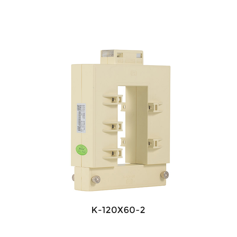 AKH-0.66/K Series Split Core Current TransformersSplit-core CTs clamp onto existing busbars for retrofit metering and protection, with 1 A or 5 A secondary outputs and multiple window sizes.View Product →
Finish with the phase pairing. On a three-phase meter the L1 voltage path must sit with the L1 current path; when two phases are crossed, one element reads negative power and the power factor looks like a random number.
A clean factor of error is a configuration problem, not a hardware one. If the total is five or ten times off, compare the CT nameplate ratio with the value programmed into the meter, then check whether the platform applies a multiplier the meter already applied. Applying the ratio twice is the classic reason a 40 kWh day appears as 400 kWh.
The same logic applies to register decoding. Modbus energy values may be 32-bit floats, two 16-bit words in a particular order, or scaled integers with a resolution of 0.1 or 0.01 kWh. One wrong choice produces numbers that look enormous, tiny or frozen, and it will not correct itself after a restart.
Check that the meter type suits the circuit as well. A direct-connected 100 A unit cannot measure a 250 A feeder within its accuracy class, and a CT-operated meter needs the matching ratio and secondary current. Prepaid models add a relay that trips on zero credit, a state often mistaken for a dead meter.
When the local display is right but the platform is empty, the fault sits in the signal path. On RS485 the most common mistake is a swapped A and B pair, followed by a star topology instead of a daisy chain, missing termination at the physical ends of a long bus, and no shared reference between devices.
Polling faster than a device can answer produces timeouts that look like broken hardware, so widen the timeout before replacing anything. On wireless installations, check signal strength first: LoRaWAN nodes on the 868 MHz band need gateway coverage and must respect duty-cycle limits, WiFi models generally need a 2.4 GHz network, and 4G units need a valid APN.
 AWT100 Smart Gateway Data Transfer Unit for IoT Energy MonitoringConnects up to 25 meters, RTUs, or PLCs over RS485 and relays data via 4G, WiFi, Ethernet, LoRa, or LoRaWAN.View Product →
A managed IoT energy management solution shortens this stage, because the gateway reports link status and buffers missed polls instead of dropping them silently.
Accuracy class is only valid inside a current range. A meter rated from 5 percent of base current upward is not accurate below that, and a direct-connected 100 A meter may register nothing at all when the only load is a 1 A standby circuit. Readings that appear and vanish with the load are usually a range problem rather than a fault.
Harmonics distort the relationship between what the meter records and what the equipment consumes. Triplen harmonics add in the neutral, so a neutral current higher than any phase current is a normal symptom of a distorted load rather than a wiring error. A Class A analyzer logging to IEC 61000-4-30 separates the fundamental from the total RMS and shows whether the distortion is the site's problem or the meter's.
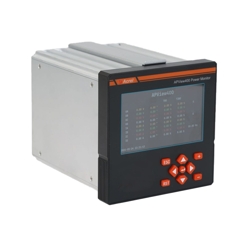
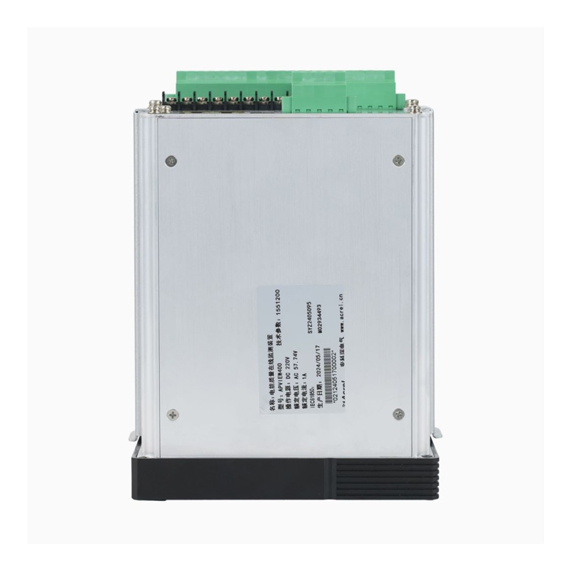 APView400 Class A Power Quality AnalyzerCertified to IEC 61000-4-30 Ed3 Class A, it records disturbance waveforms and SOE events for power-quality monitoring up to 35 kV.View Product →
On DC systems such as EV chargers and battery racks, check polarity, the shunt and the insulation monitoring device before condemning a meter. DC insulation monitors report earth faults that no energy register can show, and an insulation alarm is often read as a metering failure.
The order below resolves most callouts without opening the same terminal cover twice.
A clean 50 percent error usually comes from a ratio programmed at twice the nameplate value, a conductor passed through the CT window twice, or one phase element left unused. Check the programmed ratio first.
Yes. A loose S1 or S2 connection, or a split core that only partly closes, adds contact resistance that changes with load and temperature, so the reading jumps instead of failing outright.
Almost never. Start at the communication layer: data pair, address, baud rate, parity, timeout and gateway status. A meter that answers locally is a healthy meter.
Within the declared accuracy class and current range, a deviation of roughly ±1 percent against a reference is normal for a Class 1 meter. Outside the rated range, no comparison is meaningful.
Most of the faults above are created on installation day and discovered months later. A short commissioning record prevents both: the CT ratio, serial number, phase assignment and programmed ratio for every circuit, plus a baseline screenshot of voltage, current and power factor at a known load.
Set an alarm threshold of around ±10 percent between the meter total and the utility or sub-meter reading, so a drifting ratio is caught in days rather than at the end of a billing year. Keep the Modbus register map with the panel documentation, and the next person to troubleshoot the site will not have to guess the scaling.
If the checks above still leave a reading that will not add up, the answer usually sits in the specification rather than the wiring. Send our applications engineers the single line diagram, the CT nameplates and a screenshot of the register map, and we will tell you which of the five causes applies to your site and which is a dead end.
Contact the Acrel team with your project details and get a metering assessment covering CT selection, accuracy class and communication design in one pass.


 Email: [email protected]
 Phone: +86-18702106858 / +86-21-69156352
No.253 Yulv Road, Jiading District, Shanghai, PRC 201801


