How Do Energy Meters Work? A Comprehensive Technical Guide
Every time a household appliance runs, a factory machine operates, or a commercial building draws power from the grid, an invisible process of measurement takes place in real time. The device responsible for this measurement is the energy meter — one of the most consequential yet least understood instruments in modern electrical infrastructure. This article provides a comprehensive technical and practical exploration of how energy meters work, what components drive their accuracy, and why they matter to everyone from residential consumers to industrial engineers.
What Does Energy Meter Mean and Why It Matters
An energy meter, at its most fundamental level, is a device that quantifies the amount of electrical energy consumed by a circuit or system over a defined period of time. The term "energy meter means" different things in different contexts — in residential settings it refers to the utility meter mounted outside homes, while in industrial applications it can describe a sophisticated power quality analyzer embedded within distribution panels.
The unit of measurement is the kilowatt-hour (kWh), representing one kilowatt of power consumed continuously for one hour. A single kWh is enough to run a modern laptop for roughly 10 hours, power an LED television for about 6 hours, or operate a standard washing machine through one full cycle. These practical benchmarks illustrate why accurate energy measurement is foundational to energy management, billing systems, and conservation efforts.
From a systemic standpoint, energy meters serve three core functions:
Billing and revenue protection — utilities rely on meter readings to generate accurate invoices for electricity consumption.
Demand monitoring — industrial and commercial facilities use sub-metering to identify peak load periods and optimize energy procurement.
Power quality analysis — advanced meters detect anomalies such as voltage sags, harmonic distortion, and power factor deviation.
The Evolution From Electromechanical to Electronic Energy Meters
Understanding how modern energy meters work requires a brief look at their historical development. For most of the 20th century, the dominant technology was the electromechanical induction meter — a device that used a rotating aluminum disc to accumulate energy consumption mechanically. The disc's rotational speed was proportional to the power being consumed, and the total number of revolutions translated directly to energy units recorded on a mechanical register.
The shift to fully electronic energy meters began in earnest during the 1990s and accelerated through the 2000s. These solid-state devices replaced the rotating disc with semiconductor-based sensors and digital signal processors, offering several key advantages: no moving parts meant virtually zero mechanical wear, the ability to measure reactive and apparent power (not just active power), and compatibility with digital communication protocols.
Today, smart meters represent the frontier of this evolution. They combine the measurement precision of electronic meters with two-way communication capabilities, enabling utilities to read consumption data remotely, implement time-of-use tariffs, and detect outages automatically. In many countries, smart meter deployment has exceeded 50% of all residential installations, with some regions approaching near-universal coverage.
Core Components of an Electronic Energy Meter
To understand how an electric energy meter works, it is essential to examine its internal architecture. A modern electronic meter is composed of several interdependent subsystems, each responsible for a distinct phase of the measurement process.
Voltage Sensing Circuit
The voltage sensor monitors the line voltage continuously. In most residential and light commercial meters, a resistive voltage divider scales the mains voltage (typically 120V or 230V) down to a safe, measurable millivolt range. In medium- and high-voltage applications, voltage transformers (VTs) or capacitive voltage dividers perform the same function at higher isolation levels.
Precision is critical here: even a 0.1% error in voltage sensing propagates directly into the final energy calculation. High-end meters use laser-trimmed thin-film resistor networks with temperature coefficients below 10 parts per million per degree Celsius (ppm/C) to maintain accuracy across the full operating temperature range.
Current Transformer and Current Sensing
Measuring current safely and accurately in an energized circuit presents unique engineering challenges. The most widely used solution is the current transformer (CT), a toroidal coil through which the main conductor passes. The CT produces a scaled-down secondary current proportional to the primary line current — typically in the range of 0 to 5 amperes regardless of the primary rating.
For meters requiring high accuracy at very low current levels, Rogowski coils offer a linear response across a wide dynamic range (from milliamperes to thousands of amperes) without saturation. Hall-effect sensors provide another alternative, particularly useful in DC-coupled or mixed AC/DC environments such as EV charging stations.
The table below summarizes the primary current sensing technologies used in energy meters:
Sensing Technology
Operating Principle
Typical Accuracy
Best Application
Current Transformer (CT)
Electromagnetic induction
Class 0.2 – 0.5
AC grid metering
Rogowski Coil
Mutual inductance (air core)
Class 0.1 – 0.5
Wide-range AC measurement
Shunt Resistor
Ohm's law voltage drop
Class 0.2 – 1.0
Low-current precision metering
Hall Effect Sensor
Magnetic field detection
Class 0.5 – 2.0
DC and mixed AC/DC systems
Analog-to-Digital Converter (ADC)
Both the voltage and current signals, once scaled to appropriate levels, are fed into a high-resolution analog-to-digital converter (ADC). This component samples the waveforms thousands of times per second — typical energy metering ICs sample at 3,200 to 8,000 samples per second — converting the continuous analog signals into discrete digital values that a processor can work with.
Resolution matters enormously: a 16-bit ADC can distinguish approximately 65,536 discrete levels, while a 24-bit ADC offers over 16 million levels. Higher resolution translates directly to better measurement accuracy at low loads, which is particularly important for detecting standby power consumption in modern appliances.
Digital Signal Processor (DSP) and Metering IC
The heart of an electronic energy meter is the metering integrated circuit (IC), which contains a dedicated DSP optimized for power and energy calculations. This processor continuously multiplies the instantaneous voltage and current samples together to compute instantaneous power, then integrates this over time to derive accumulated energy.
Modern metering ICs also calculate reactive power, apparent power, power factor, frequency, and harmonic content — all within the same device. This multi-parameter capability is what distinguishes an advanced electric energy meter from a simple kilowatt-hour counter.
Display and Communication Interfaces
Processed data is presented on an LCD display showing accumulated kWh, and in smart meters, transmitted through one or more communication channels. Common communication interfaces include:
DLMS/COSEM — the international standard protocol for meter data exchange
Modbus RTU/TCP — widely used in industrial sub-metering applications
M-Bus — a European standard designed for wired meter reading networks
RF mesh networks (915 MHz / 2.4 GHz) — used in Advanced Metering Infrastructure (AMI)
PLC (Power Line Communication) — transmits data over existing electrical wiring
Cellular (LTE-M / NB-IoT) — enables direct cloud connectivity for remote meters
How Does an Energy Meter Work: The Measurement Process Step by Step
The question of how does an energy meter work can be answered by tracing the path of electrical signals from the incoming mains supply through to the final accumulated reading. The process involves both analog and digital stages, each performing specific transformations on the electrical signal.
Step 1: Signal Acquisition
The process begins with the simultaneous acquisition of voltage and current signals from the electrical supply. The voltage divider or transformer produces a scaled replica of the line voltage, while the CT or other current sensor generates a proportional representation of the load current.
Step 2: Signal Conditioning
Raw sensor outputs typically contain noise and are at voltage levels incompatible with the ADC input range. Anti-aliasing filters remove high-frequency components above the Nyquist frequency, preventing measurement artifacts. Precision amplifiers then scale the signals to the optimal ADC input range, maximizing resolution and minimizing quantization error.
Step 3: Analog-to-Digital Conversion
The conditioned signals are digitized at a high sampling rate. A phase-locked loop (PLL) circuit ensures that voltage and current sampling remain synchronized, which is critical for accurate phase angle measurement. Any timing offset between the voltage and current sampling paths introduces phase errors that directly affect active and reactive power accuracy.
Step 4: Digital Computation
The metering IC multiplies corresponding voltage and current samples to compute instantaneous power values. These are summed over a defined interval (typically one cycle of the mains frequency) to produce a mean power value. The processor then accumulates these power readings over time, converting to energy in watt-hours using internal precision timers calibrated against a crystal oscillator.
Step 5: Output and Reporting
The accumulated energy value is written to non-volatile memory (EEPROM or Flash) at regular intervals to preserve data in the event of power interruption. The LCD display updates periodically, and in smart meters, data packets are transmitted over the communication interface on a schedule defined by the utility (commonly every 15, 30, or 60 minutes).
How Do Energy Meters Work for Three-Phase Power Systems
Residential consumers typically use single-phase power, but commercial buildings, industrial facilities, and large HVAC systems operate on three-phase supplies. Understanding how do energy meters work in three-phase configurations reveals additional complexity and important design considerations.
A three-phase energy meter contains three independent voltage sensing channels and either two or three current measurement channels (depending on whether the neutral conductor is metered). Each phase pair is measured independently, and the total energy is the algebraic sum of the three phase contributions.
For balanced three-phase loads — where all three phases carry equal current — a simplified two-element meter can be used. However, in industrial environments where loads are frequently unbalanced, a full three-element (three-phase, four-wire) meter is required to maintain accuracy. Failure to account for phase imbalance can produce measurement errors of 15% or more in severely unbalanced systems.
Key accuracy metric: Under IEC 62053-22, Class 0.5S meters (designed for high-accuracy sub-metering) must maintain accuracy within ±0.5% across the range from 1% to 120% of nominal current, and across power factors from 0.5 lagging to unity. This specification ensures reliable measurement even during low-load overnight periods.
Reactive and Apparent Power Measurement
Beyond active power (kWh), industrial meters routinely measure reactive power (kVARh) and apparent power (kVAh). Reactive power arises from inductive loads such as motors and transformers, which cause the current waveform to lag the voltage. While reactive power does not perform useful work, it must still flow through the network and contributes to conductor heating and transformer loading.
The power factor — the ratio of active to apparent power — is a key efficiency indicator. A power factor of 1.0 means all consumed power is performing useful work; a power factor of 0.7 means that 43% more current must flow to deliver the same useful power. Many utilities apply power factor penalty charges to large commercial and industrial customers with sustained power factors below 0.9.
Smart Meters and Advanced Metering Infrastructure
The electricity energy meter has undergone its most dramatic transformation in the past two decades through the development of smart metering. A smart meter is not simply an electronic meter with a communication module bolted on — it represents a fundamental rethinking of the meter's role in the energy system.
Bidirectional Energy Measurement
Traditional meters only measure energy flowing from the grid to the consumer. Smart meters track energy flow in both directions, which is essential for prosumers — customers who both consume energy from the grid and export surplus generation from rooftop solar panels or battery systems. Net energy metering (NEM) schemes, used in many jurisdictions to compensate solar owners, depend entirely on accurate bidirectional measurement.
Interval Data and Load Profiling
Rather than simply accumulating a single kWh total, smart meters record consumption in 15- or 30-minute intervals, creating a detailed load profile throughout the day. This granular data enables:
Time-of-use (TOU) tariffs that charge higher rates during peak demand periods
Demand response programs that incentivize load shifting away from peak hours
Non-intrusive load monitoring (NILM) algorithms that can identify individual appliance behavior from aggregate consumption patterns
Predictive maintenance alerts based on unusual consumption signatures
Tamper Detection and Security
An energy watt meter in a smart grid environment must be resistant to both physical and cyber tampering. Modern smart meters incorporate magnetic field sensors that detect the presence of external magnets (which can interfere with CT measurements), event loggers that record cover openings and power outages, and encrypted communication channels using AES-128 or AES-256 standards. Revenue protection features in smart meters have been shown to reduce meter fraud by 70–90% compared to older electromechanical devices.
Data Security and Privacy
Interval energy data is surprisingly revealing — analysis of 15-minute consumption records can identify when residents wake up, which appliances they use, and even the number of occupants in a household. Responsible smart meter deployments include data encryption both at rest and in transit, user consent mechanisms for data sharing, and retention policies that limit access to historical interval data.
Accuracy Classes and Calibration of Energy Meters
Not all energy meters are created equal. International standards define accuracy classes that set maximum permissible errors for meters used in different applications. Understanding these classes is essential for anyone specifying meters for industrial, commercial, or utility applications.
Accuracy Class
Max Error at Full Load
Standard
Typical Application
Class 0.2S
±0.2%
IEC 62053-22
Revenue reference / custody transfer
Class 0.5S
±0.5%
IEC 62053-22
Industrial sub-metering
Class 1
±1.0%
IEC 62053-21
Commercial / general purpose
Class 2
±2.0%
IEC 62053-21
Residential utility billing
Class 3
±3.0%
IEC 62053-11
Electromechanical / legacy systems
Calibration Procedures
Energy meters are calibrated at the factory using reference standards traceable to national metrology laboratories. The calibration process involves injecting precisely known voltages and currents at multiple test points — typically at 5%, 25%, 50%, 100%, and 120% of rated current — and at multiple power factors including unity (1.0), 0.8 lagging, and 0.5 lagging.
Calibration constants are stored in the meter's non-volatile memory and applied during every measurement cycle. Most jurisdictions require periodic re-verification of meters in service — commonly every 5 to 16 years depending on the meter class and national regulations — to confirm that calibration has not drifted due to component aging.
Sources of Measurement Error
Even well-calibrated meters can exhibit errors under certain conditions. Common sources of measurement error include:
Temperature drift — component characteristics shift with temperature; well-designed meters compensate through temperature sensors and correction algorithms
Harmonic distortion — non-linear loads such as variable frequency drives and switching power supplies introduce harmonics that some meters fail to account for correctly
CT saturation — excessively high fault currents can temporarily saturate a CT, causing measurement errors during that period
Burden impedance — excessive resistance in CT secondary wiring changes the apparent burden and affects accuracy
Electromagnetic interference (EMI) — strong external fields from nearby equipment can induce measurement artifacts in insufficiently shielded designs
Power Consumption Tracking in Industrial and Commercial Settings
While utility-grade billing meters represent the most visible application of energy measurement, sub-metering within commercial and industrial facilities has grown into a significant discipline in its own right. Power consumption tracking at the circuit, equipment, or process level provides the granular data necessary for meaningful energy management programs.
Sub-Metering Architectures
A typical industrial sub-metering installation places individual meters on major load groups — HVAC systems, lighting circuits, process machinery, compressed air systems, and IT infrastructure. These meters communicate over a building automation system (BAS) or industrial network to a central energy management system (EMS) that aggregates, visualizes, and analyzes consumption data.
The return on investment for sub-metering programs is well-documented. Studies across commercial buildings in North America and Europe consistently show that organizations with comprehensive sub-metering and active energy management reduce consumption by 10–20% within the first year of implementation, primarily through behavioral changes and identification of waste sources that were invisible without measurement.
Demand Management and Peak Shaving
For large electricity consumers, demand charges — fees based on the peak power level recorded during each billing period — can represent 30–50% of total electricity costs. Energy meters with demand measurement capability record the highest average power in any 15-minute window during the billing period, and this peak demand figure drives the demand charge.
Real-time monitoring of demand data allows facilities to implement peak shaving strategies: temporarily curtailing non-critical loads when demand is approaching the threshold that would trigger a higher demand charge. Automated demand response systems, triggered by signals from the energy meter's communication output, can reduce peak demand by 10–25% in well-managed facilities.
Power Quality Monitoring
Advanced energy meters incorporate power quality monitoring functions that go beyond simple kWh accumulation. Key parameters include:
Total Harmonic Distortion (THD) — measures distortion of voltage or current waveforms from the ideal sinusoidal shape
Voltage sag/swell detection — identifies transient voltage deviations that can damage sensitive equipment
Flicker measurement — quantifies rapid fluctuations in voltage that cause visible light flicker
Unbalance — measures asymmetry between phases in three-phase systems
Frequency deviation — monitors grid frequency stability
Comparing Single-Phase and Three-Phase Energy Meters
Single-Phase Meter
One voltage channel, one current channel
Typical voltage: 120V (North America) / 230V (Europe)
Load range: 5A – 100A typical
Used in residential and light commercial
Simpler calibration and testing
Lower cost per installation point
Cannot detect phase imbalance
Three-Phase Meter
Three voltage channels, two or three current channels
Typical voltage: 400V L-L (Europe) / 208V or 480V (North America)
Load range: 5A – 6000A with external CTs
Used in commercial, industrial, and utility applications
Measures per-phase and aggregate parameters
Higher cost, more complex wiring
Full visibility of phase imbalance conditions
Installation, Safety, and Regulatory Compliance
Proper installation is as important as meter quality for accurate power consumption tracking. Incorrectly installed meters can produce systematic errors that persist undetected for years, resulting in overbilling or underbilling and masking actual consumption patterns.
Key Installation Considerations
CT orientation — current transformers must be installed with the primary conductor passing through the window in the correct direction, and the polarity marked terminal connected to the correct secondary wire. Reversed CT polarity causes the meter to subtract rather than add measured energy.
CT burden — the total resistance of secondary wiring must fall within the manufacturer's specified burden range; excessive burden degrades accuracy and can cause CT overheating.
Voltage connection sequence — in three-phase meters, voltage and current inputs must be connected in matching phase sequence; mismatched connections cause large measurement errors or reverse energy registration.
Grounding and shielding — signal wiring should be shielded and grounded at one end to minimize EMI pickup, particularly in noisy industrial environments.
Regulatory Standards
Energy meters used for billing purposes must comply with national and international standards that govern accuracy, safety, environmental performance, and electromagnetic compatibility. Key standards include:
IEC 62052-11 — general requirements for electricity metering equipment
IEC 62053-21/22/23 — accuracy requirements for active and reactive energy meters
ANSI C12.1 / C12.20 — North American electricity meter code and accuracy standards
EN 50631-1 — smart metering functional requirements for European markets
MID (Measuring Instruments Directive) — EU framework for legal metrology approval of utility meters
Frequently Asked Questions
Q1: What is the basic principle behind how an energy meter measures electricity?
An energy meter measures electricity by simultaneously sensing the voltage across and current through a circuit, multiplying these instantaneous values to calculate power, and then integrating (summing) that power over time to derive energy in kilowatt-hours. In electronic meters, high-speed analog-to-digital converters sample both signals thousands of times per second, and a dedicated metering chip performs the calculations in real time.
Q2: What is the difference between an energy meter and a watt meter?
A watt meter measures instantaneous power at a specific moment in watts (W) or kilowatts (kW). An energy meter, by contrast, accumulates power consumption over time and reports the total in kilowatt-hours (kWh). Think of a watt meter as a speedometer — showing current rate — while an energy meter is like an odometer, recording total distance traveled over time.
Q3: How accurate are modern residential energy meters?
Modern electronic residential energy meters typically comply with IEC Class 1 or Class 2 accuracy standards, meaning maximum errors of ±1% or ±2% respectively under specified test conditions. In practice, well-maintained meters installed correctly often achieve errors below ±0.5% across the normal load range. The greatest accuracy challenges occur at very low load levels (below 1–5% of rated current) and in the presence of significant harmonic distortion.
Q4: Can an energy meter be affected by external magnets?
External permanent magnets can interfere with current transformer-based measurement by partially saturating the CT core, which reduces the effective permeability and changes the transformation ratio. In older electromechanical meters, strong magnets could slow the disc rotation. Modern smart meters incorporate magnetic field sensors that detect tampering attempts and log them as security events, making this form of interference both detectable and recorded.
Q5: What does energy meter mean in the context of solar or renewable energy systems?
In renewable energy systems, an energy meter (or bidirectional meter) must measure energy flow in both directions: energy consumed from the grid and energy exported to the grid from the solar installation. These meters record import and export registers separately, enabling net metering calculations that determine whether a customer receives a credit or owes a payment for net energy over the billing period.
Q6: How often does a utility energy meter need to be replaced or recalibrated?
Replacement and recalibration intervals vary by jurisdiction and meter technology. Many national metrology authorities mandate re-verification every 5–16 years for utility billing meters. Modern electronic meters have a designed operational life of 15–20 years. Rather than periodic recalibration of individual meters in the field, most utilities now use statistical sampling programs that test a representative sample of meters from each population and replace entire cohorts if out-of-tolerance rates exceed a defined threshold.
Q7: What is the role of a current transformer in an energy meter?
The current transformer (CT) safely scales down the large line current — which may be hundreds or thousands of amperes — to a small, standardized secondary current (typically 0–5 amperes) that the meter's measurement electronics can safely handle. Without the CT, high line currents would need to pass directly through the meter's circuitry, creating severe safety hazards and component sizing challenges. The CT also provides galvanic isolation between the high-voltage primary circuit and the meter electronics.
Q8: How do smart meters communicate data to utilities?
Smart meters use one or more communication technologies depending on the utility's AMI infrastructure. The most common approaches are RF mesh networks (operating at 902–928 MHz or 2.4 GHz), which form self-healing wireless networks throughout a neighborhood; power line communication (PLC), which modulates data signals onto the existing power wires; and cellular technologies such as LTE-M or NB-IoT for meters in locations where RF mesh coverage is impractical. Data is encrypted end-to-end and transmitted on schedules set by the utility, typically every 15–60 minutes.

 English
 Deutsch
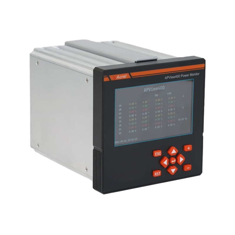 Part 1: Introduction 1.1 What is Power Quality and Why is it Important? In modern society, a stable ...View More
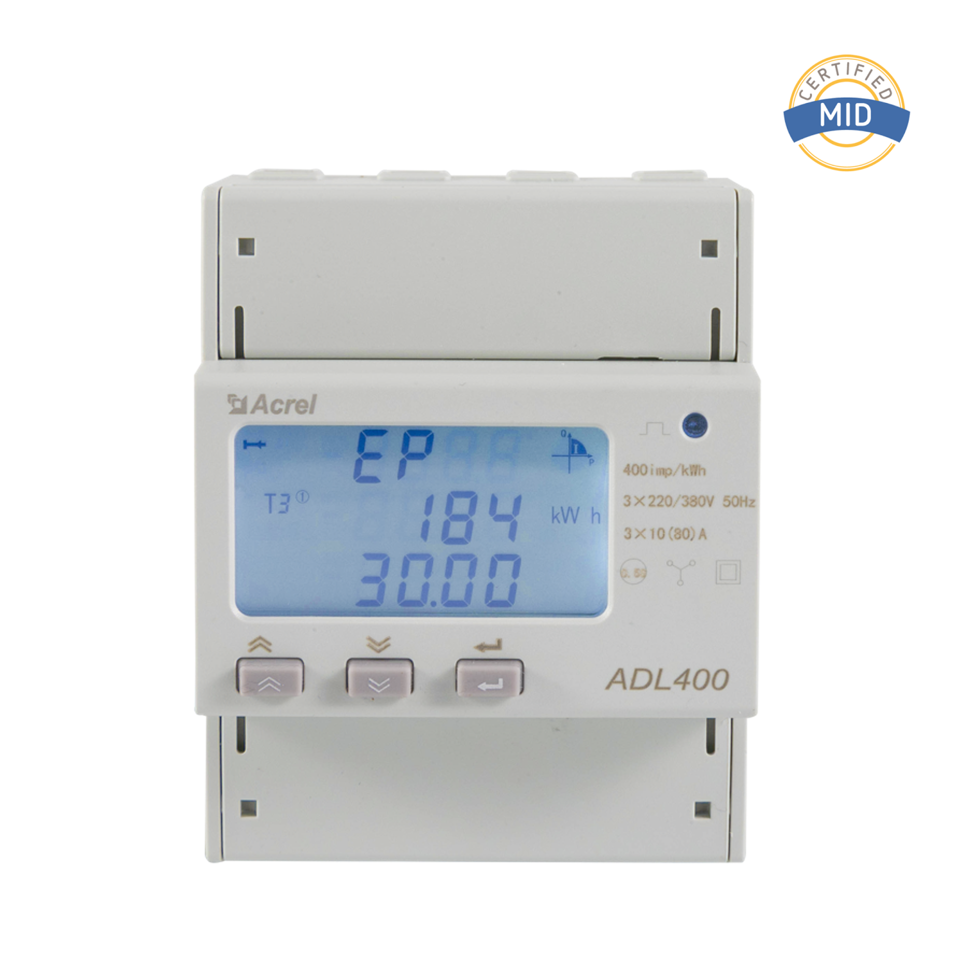 Introduction to AC Energy Meters In today’s rapidly evolving energy sector, accurate measurement and...View More
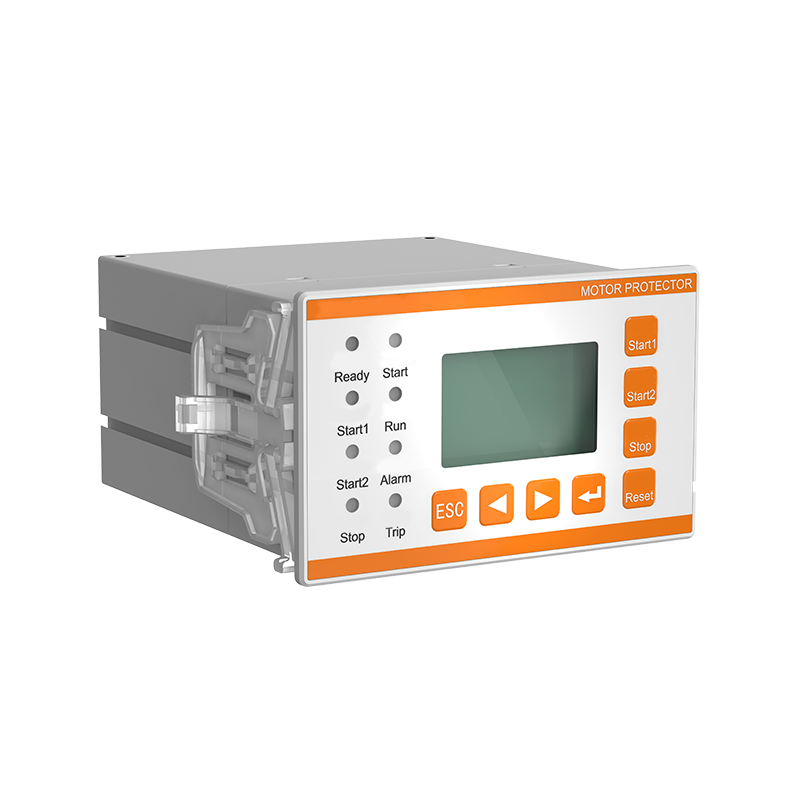 I. Introduction: The Critical Need for Motor Protection Electric motors are the undisputed workhorse...View More
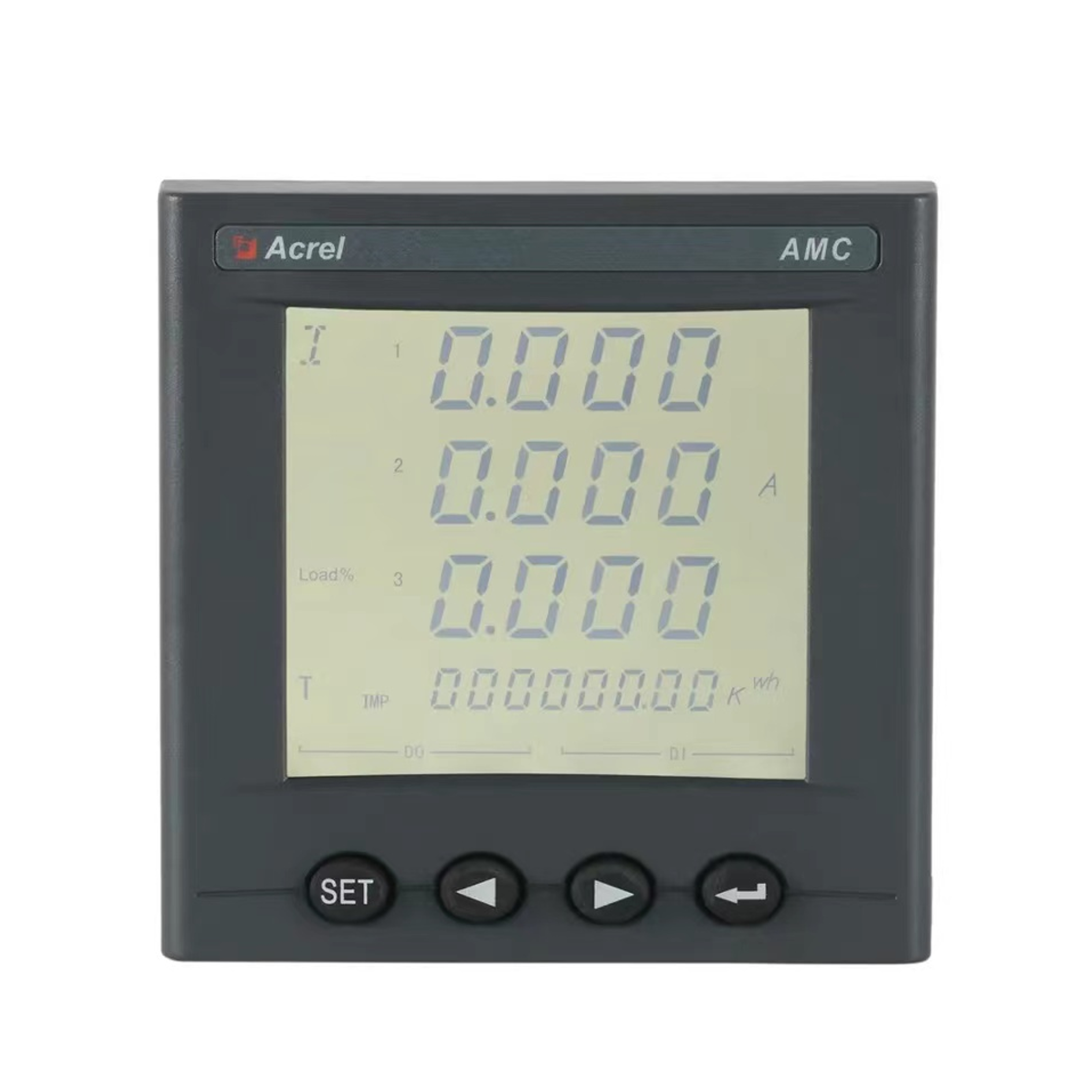 Introduction In modern industrial and commercial power environments, precise measurement and managem...View More
 Email: [email protected]
 Phone: +86-18702106858 / +86-21-69156352

